This is a short follow on from my post on Tuesday and this will just cover the same principles but focussing on using flex track for your helix.
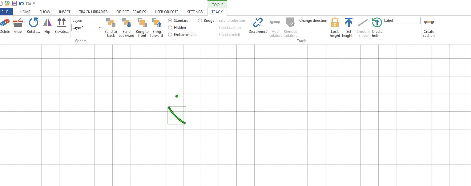
Start by selecting the type of flex track you want to use. In this example peco code 55 but the principle is pretty much the same with any type of flex or scale.
Once you have your flex track select it and then click on Curve flex … on the tool bar. The ‘Set flex curve wizard’ will pop up in N scale you can enter 90 as the angle (the max is 90) but in other larger scales you may need to use a smaller angle, maybe 45 degrees. Then enter the radius, I am goint to use 457mm or 18″ in this example.
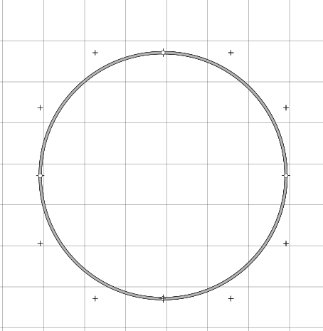
Once you have a curve you can then open the helix wizard as we did previously, make sure the track is still selected.
Enter your start and end heights, in this example 225mm (approx 9″)
As you can see I have saved time here and adjusted the turns to 3.5 which would have a slope % of 2.2% its not ideal but most N scale locomtives will run quite happily up that grade with a train. With a 914mm or 3′ radius which is going to result in a helix about 6’6″ wide you would only have a 1.1% grade. Most of us wouldn’t be able to give up over 40 sqft in our train room for this monster Helix although in HO thats quite common.
Anyway back to the helix click ok and you will have your helix on your plan. to quickly see how much track is swollowed up by the helix double click on it and you will see at the bottom of the screen the track length. here its 10,051.25mm which is over 10m(33′) of flex track in a small 3.5 turn helix.
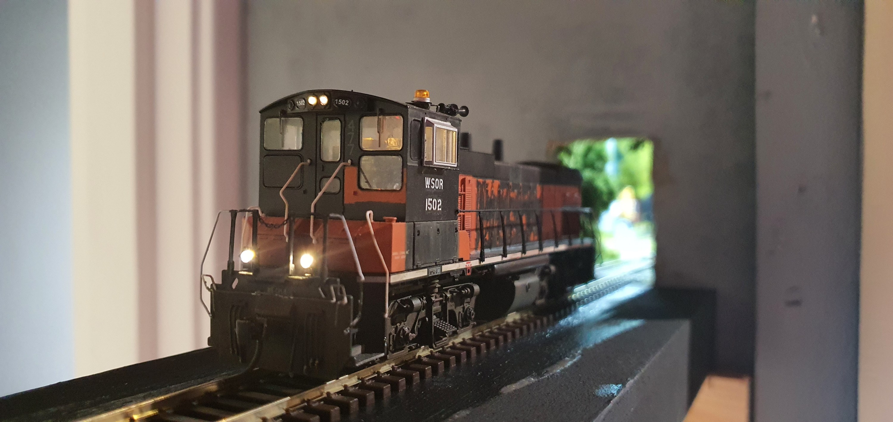
I hope this helps you add your perfect helix to your layout. The Waukesha Sub & WSOR Northern Sub N Scale layouts I am constructing will have 4 helicies (yes thats the plural of Helix) on the layout.
I now have stickers available from the GordyUK store, those in the US can even get Die Cut versions. These look awesome on your facia, toolbox or workbench.
Using software to draw your layout is becoming much more common than paper. Most like AnyRail will even tell you the quantity of materials you need to build your layout and can draw your layout in 3D.
However one of the things people often ask me how to do is draw a Helix so here we’ll cover a few short steps to have you drawing a helix using set-track or Kato Unitrack pieces.
First select the radius of curve you desire and drop it onto the work area, for this example we are using curved radius 381mm (13.75″) x 30 degree pieces so we will need 12 per circle.
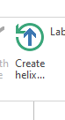
Once you have done that select the Create Helix option in the tool bar.
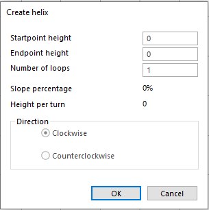
The helix wizard will open
If you have set the height of your layout then enter that as the start point height.If you haven’t then set to 0 if you enter a height thats different to the height of the track you are trying to connect to then AnyRail will prevent you connecting those sections of rail. Imagine its like having one piece of rail on a table and the other on the floor looking down it may appear you can connect them but there is vertical seperation. As we are now adding a Helix to our layout we need to remember to think in 3 dimensions.
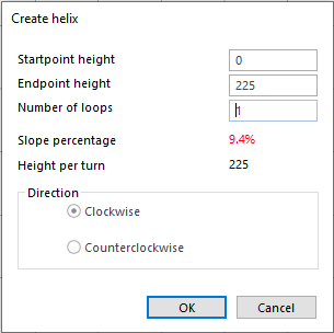
The next thing to do is enter the end point height, this will be in the same unit of measure as set for the rest of your project so if working in mm enter the value as 349.5(mm) not 13.5(inches) otherwise you’ll get some interesting slope % results. My layout is 225mm between decks so we’ll go ahead and enter 225 into the endpoint height.
As you can see the software has auto calculated the slope percentage and height per turn. I haven’t changed the number of turns so its off the scale and unlikely that any loco will pull anything up it. So next enter your turns, if you don’t know how many turns you need then enter the minimum clearence you need between decks in your choosen scale in this case its 65mm for N Scale to make sure you can get in and re-rail any cars. Remember to include the thickness of the helix material, track & roadbed in this calculation.
Divide the height per turn you want by the difference in height between the start and end points. Note you need to keep in the same unit of measure for clearance and heights so do a conversion if necessary always remember its 25.4mm to 1 inch.
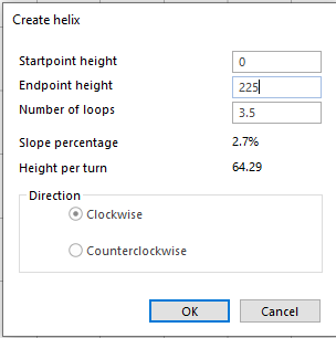
In reality we are not going to be that precise with a helix so round up or down to the quarter turn, we’ll use 3.5 turns for this helix.
So now we have a 2.7% slope helix if this is too steep for you then you have three options open to you, either increase the radius if space allows or reduce the clearance height you are happy to accept or make an oval shaped helix to add run to each turn. Its most likely that you will have to increase the radius or go for an oval helix.
For example using a huge 481mm (18.91″) radius part with the same settings gives you a slope percentage of 2.1% which is probably more appealing than nearly 3%
The last thing to do is decide if you want your Helix to run clockwise or anti clockwise, select what works best for you and hit ok. AnyRail will then build your helix for you.
Types of Helix
Its not just the slope % you need to consider in the design of your helix you also need to make sure the exit and entrance are where you want them to be on your layout. A 1 turn helix will have your train exit in the same direction it entered if there is a wall in the way thats probably not desirable. So I produced this handy Helix guide for you to use.
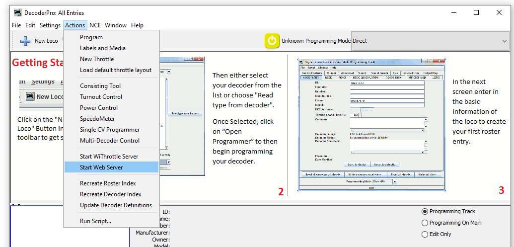
With the layout now connected to the computer we can set up a JMRI Web Server to use Wifi throttles such as a smart phone or even allow remote operations through the web.
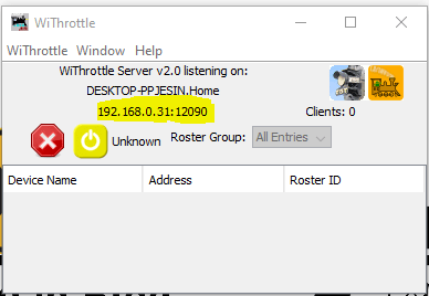
To start a web server with JMRI open and connected to the NCE system navigate to Actions>Start Wi Throttle Server
You’ll see this window note down the IP Address and port number (highlighted in yellow). In this example the IP address is 192.168.0.31 and the port is 12090. This IP address is internal to your home network, don’t panic your router firewall will prevent access to anyone from outside your home gaining access to your layout.
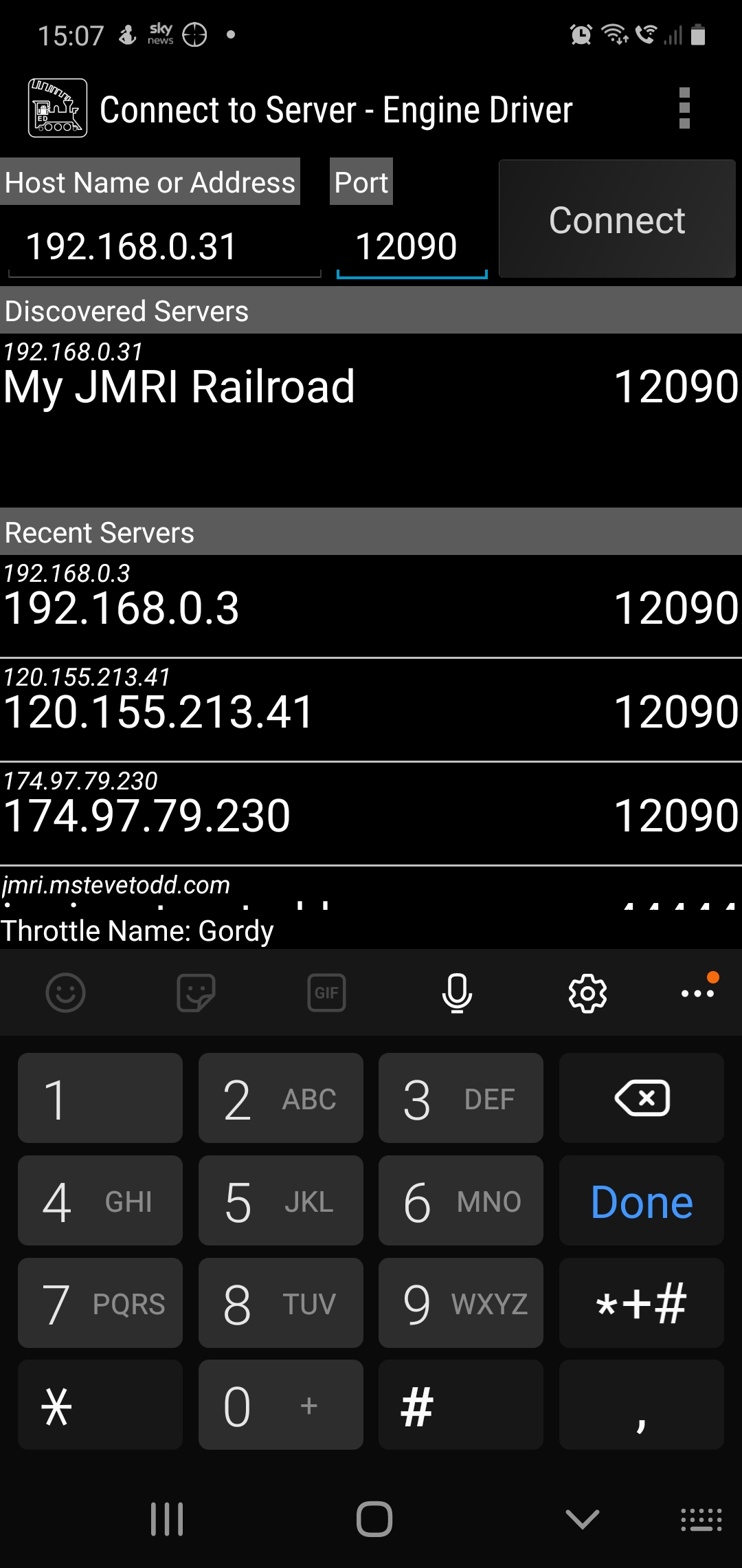
Now JMRI is running and allowing any device with WiThrottle or Engine Driver or any other supported app to connect to your computer and through it the layout. So lets in this example use the Android app Engine Driver.
When opening the app your device will either have found the server or you can enter the IP address and port number at the top as shown above. Hit connect and then you should be able to aquire a locomotive on your layout. If you have entered your roster into JMRI then you can see all locomotives in your roster rather than entering the DCC address.
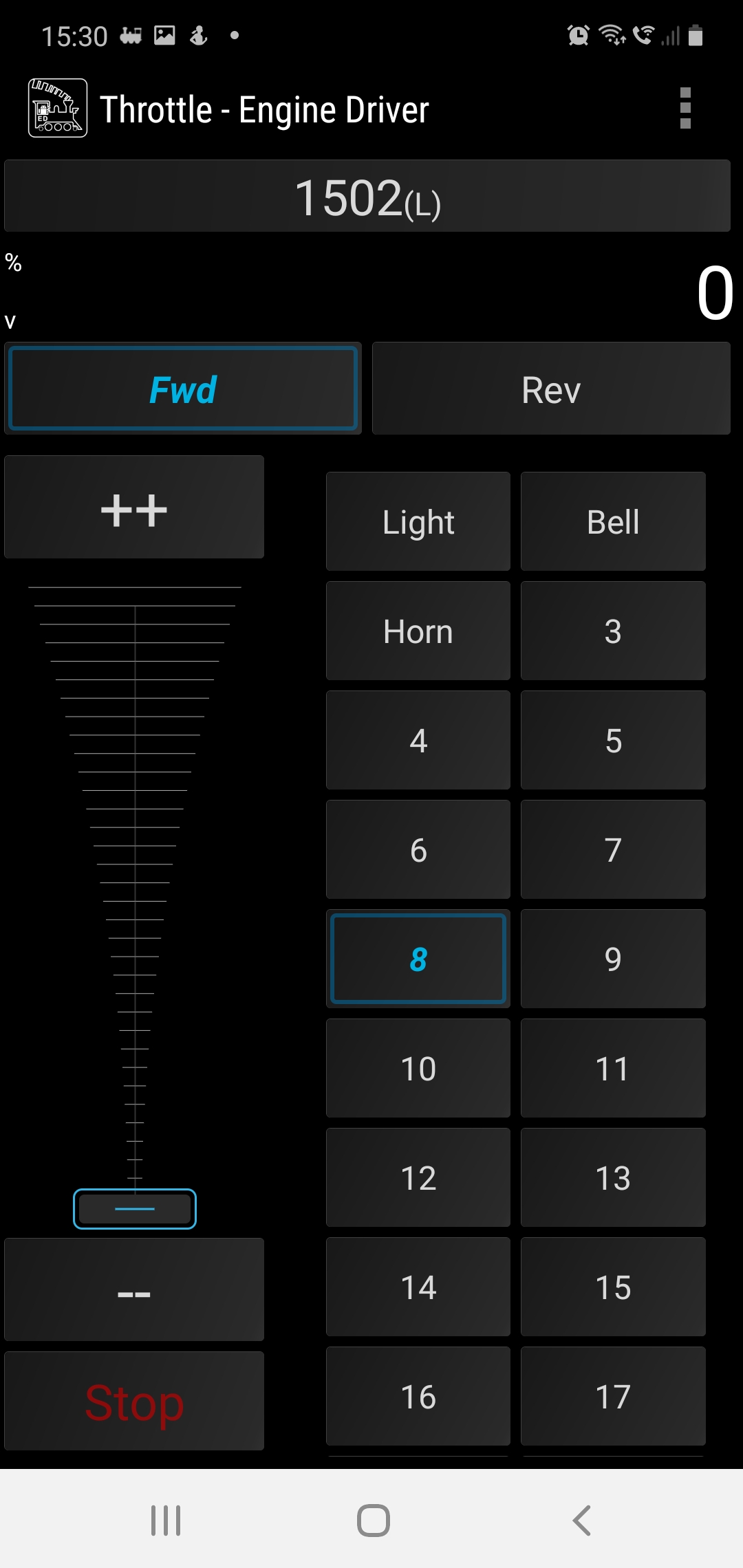
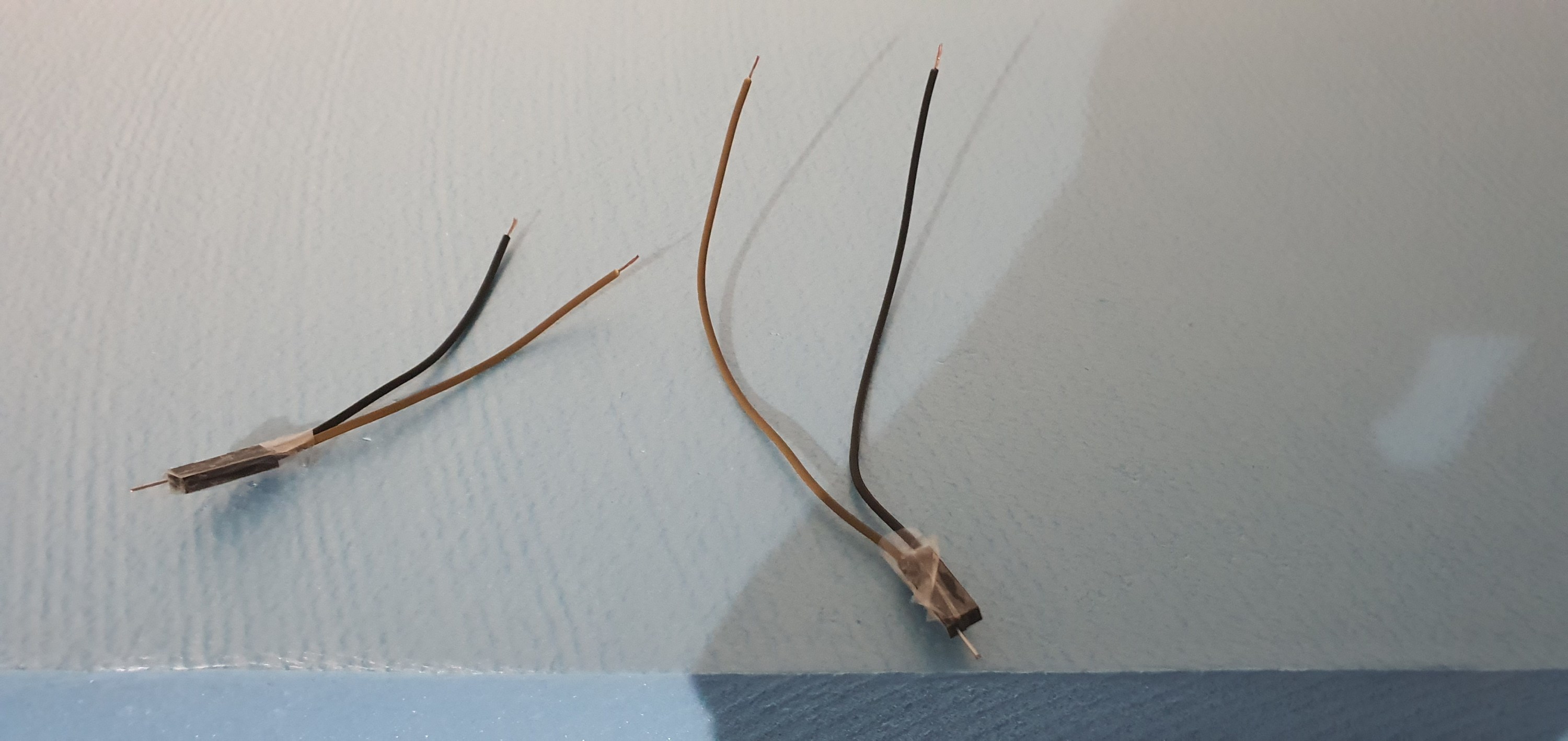
Engine Driver Throttle in Dark Mode, the loco is selected using its DCC address 1502
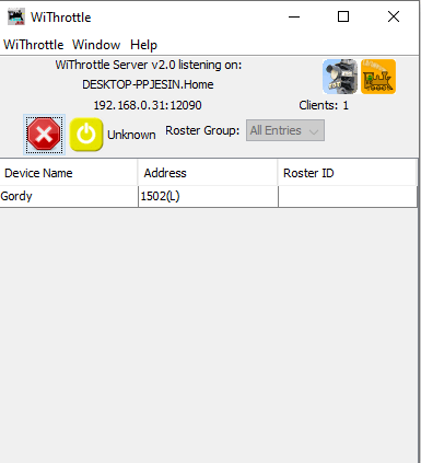
Back over on the PC we can see how many wifi throttles we have connected on the WiThrottle screen.
This is a great way to add more throttles to your layout and to the basic NCE PowerCab system which limits you to only having 4 cabs.
I hope youhave found this useful, its not a huge step from here to remote ops so we’ll cover that in a future post.
For now, stay safe and keep working on your railroads.
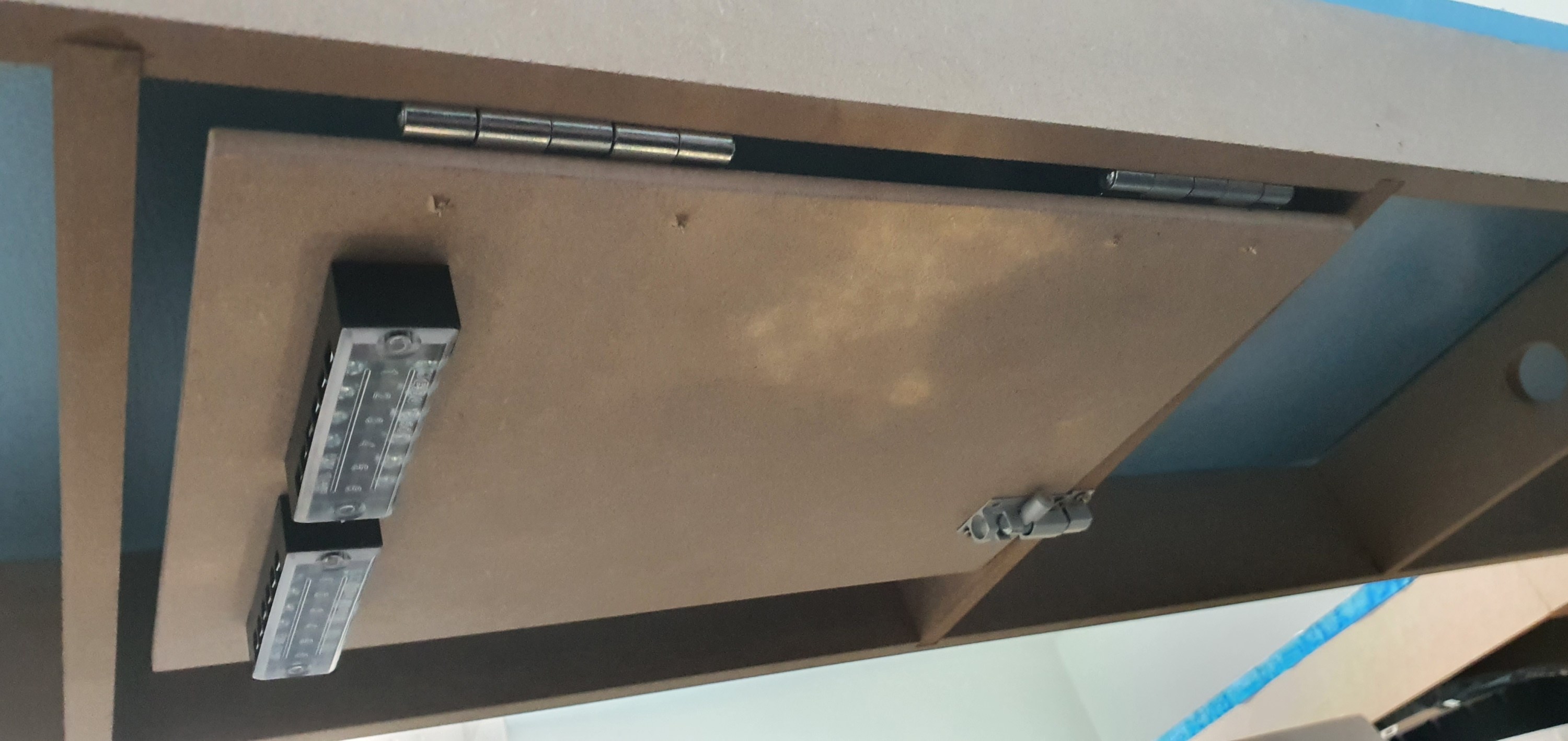
I really don’t want to have to trouble shoot electrical gremlins under my layout, who does. So I’ve designed electrical boards to mount, DCC boosters, block detection units, circuit breakers etc.
To make the boards i used A4 6mm MDF sheets from Amazon. Onto these are mounted 63mm butt hinges and 38mm barrel bolts. I threw away the supplied screws and replaced them with 3.5mmX12mm screws. All the ironmongery came from my favourite store iornmongry direct were a pack of 200 of those screws was less than £2.
To one side of the board is fitted a screw terminal block. This is really useful when wiring and prevents cutting feeders or straining wires the wire from the track comes in on one side of the wood and then the wires go from the terminal strip to the DCC components on each board keeping everything neat and tidy.
Board swung down
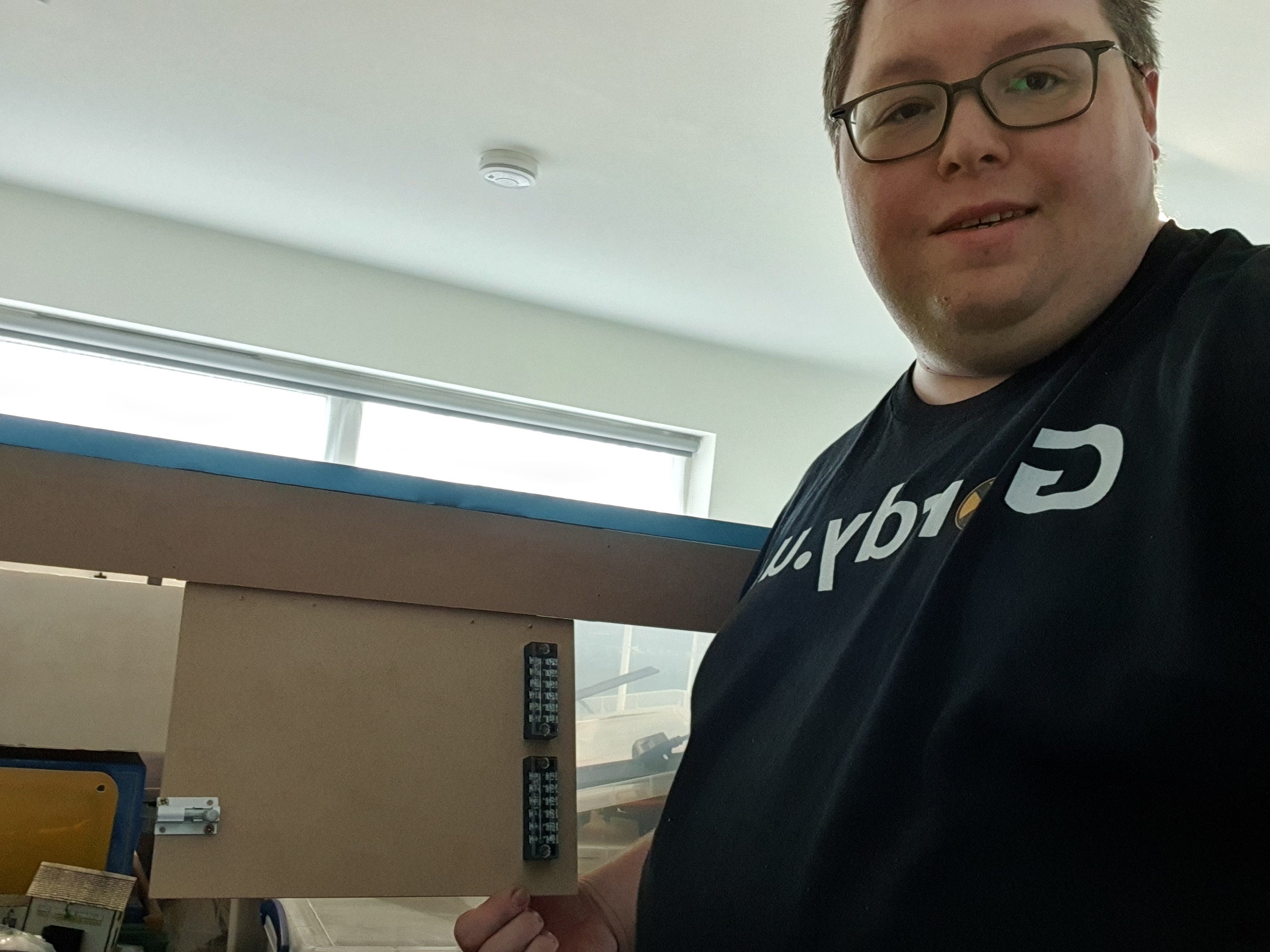
When the bolt is released the board swings down to the front of the layout at a comfortable height to work at either sitting or standing.
Well thats the prototype done. Now 9 more to get built.
This was supposed to be a nice easy post on a Friday evening followed by a beer or ten. However as with most things electronic its not gone quite to plan.
So what are we attempting to do? well in order to have the layout run from anywhere in the world it needs to talk to the computer and the plan is to do that using JMRI and a USB interface. Its usually simple and I have done this on my other layout before with no issue. Not today it would seem but anyway lets talk about the process.
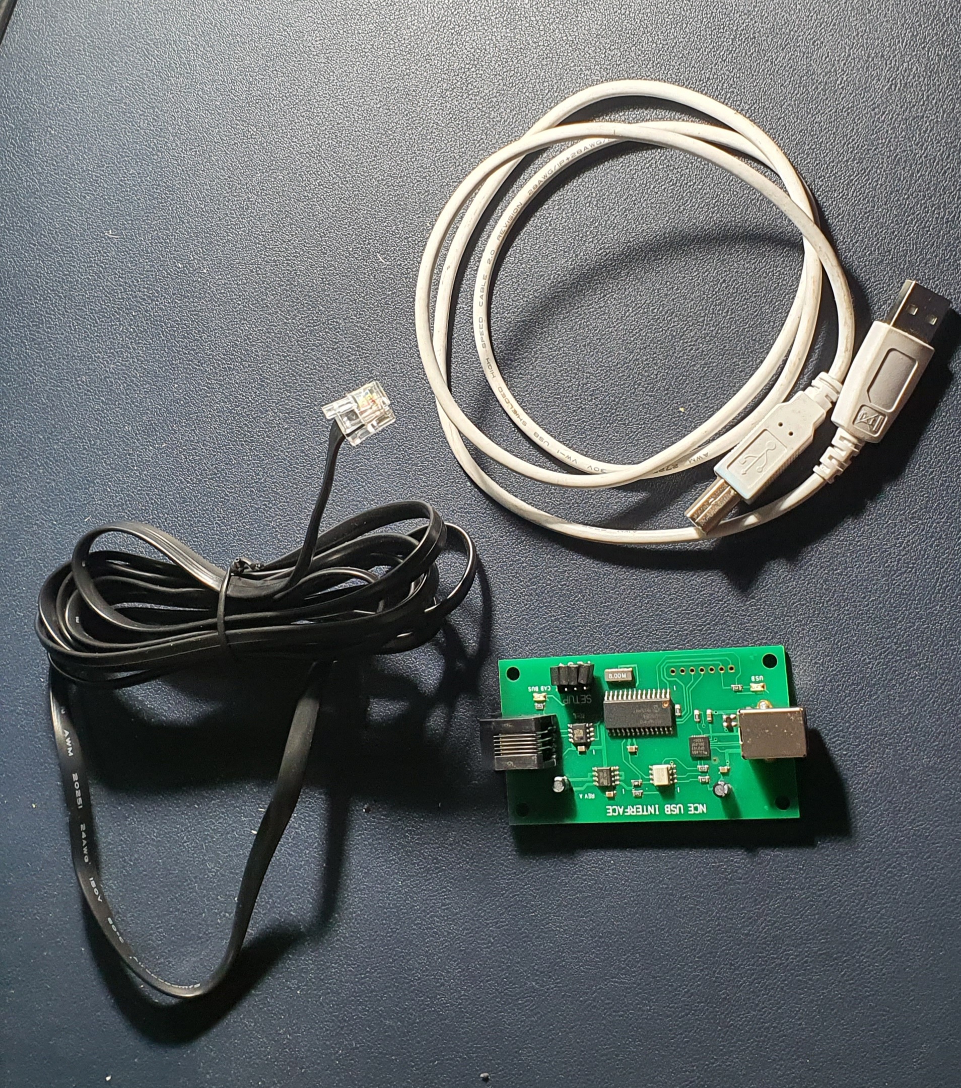
So this is what you need to interface an NCE powerCab to your PC. Its a standard NCE Cab bus cable, a NCE USB Interface and a USB A>B cable like you use for hooking up a printer.
To set up power up the Powercab and then plug the NCE USB Interface into the spare Cab socket and you should be able to detect the device when you plug it into your PC.
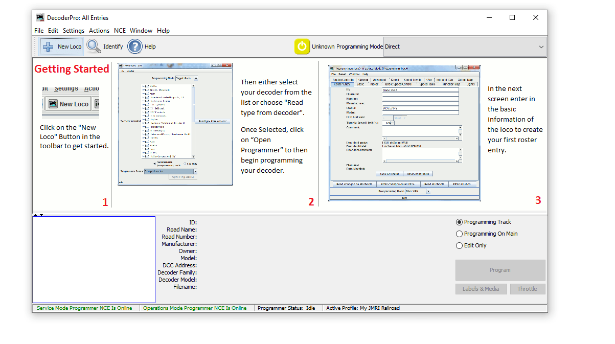
When you open JMRI you will be asked to set up connections if not go to Edit>Preferences and you’ll see connections at the top
Select NCE as the Manufacturer and NCE USB as the system connection. Its really important you select the correct COM port, if you don’t know which one to use then go to Device Manager on your PC (if windows) and find the ‘CP210x USB to UART Bridge’ thats the NCE USB device look for the com port and make sure this matches in JMRI. Save your settings and exit.
When you return to the Decoder Pro screen you should then see the two green indications at the bottom of the window. If like mine did for the best part of an hour these go red and are not connected after a few seconds but are green to start with go to JMRI downloads and update the version on your PC. Then un plug and start everything again. If its red and never green check you have selected the correct COM port.
Then to test you have control of the layout go to Actions>New Throttle you’ll get this window
JMRI Throtle Window
Select a loco on your roster thats on the layout by entering the address in the Address Panel and click on set. This will aquire the locomotive. Then see if you can use any of the functions if a sound loco Horn is always a good one to test. If thats all working then you are set up and ready to go. You can either go to the next stage and use Wifi throttles or even allow remote ops or program your locomotives..
We’ll cover the JMRI Web Server for WIFI throttles and also Remote Ops in a future blog post.
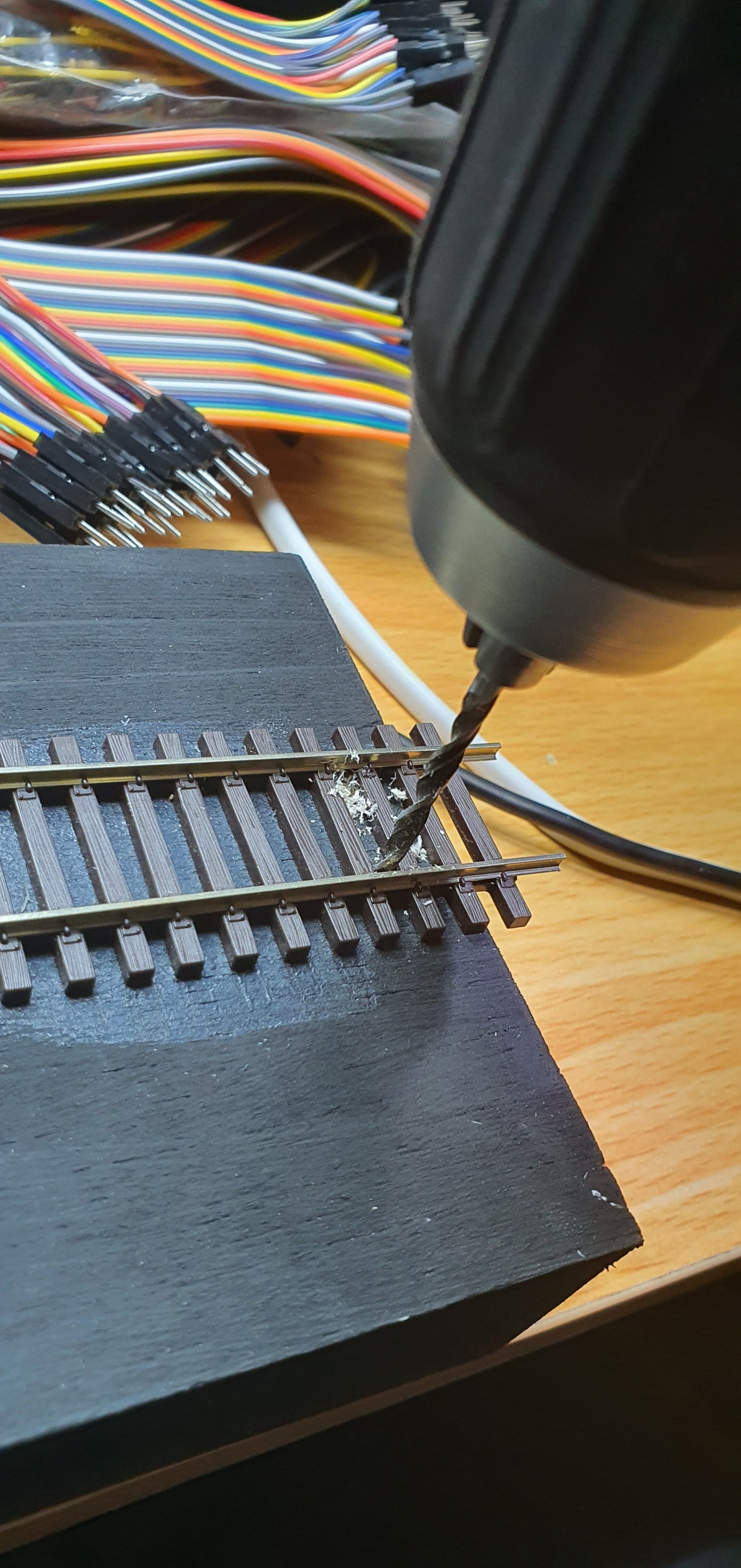
So the electrics are pretty simple here but its still worth blogging about. I guess its an improvement on the how to drill a hole post. Anyway back to it, lets get on with it, so we have a stick with a length of track on it and a DCC bus to connect it into. The thing is removeable so our project needs to be removeable as well.
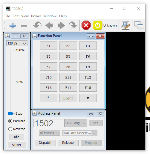
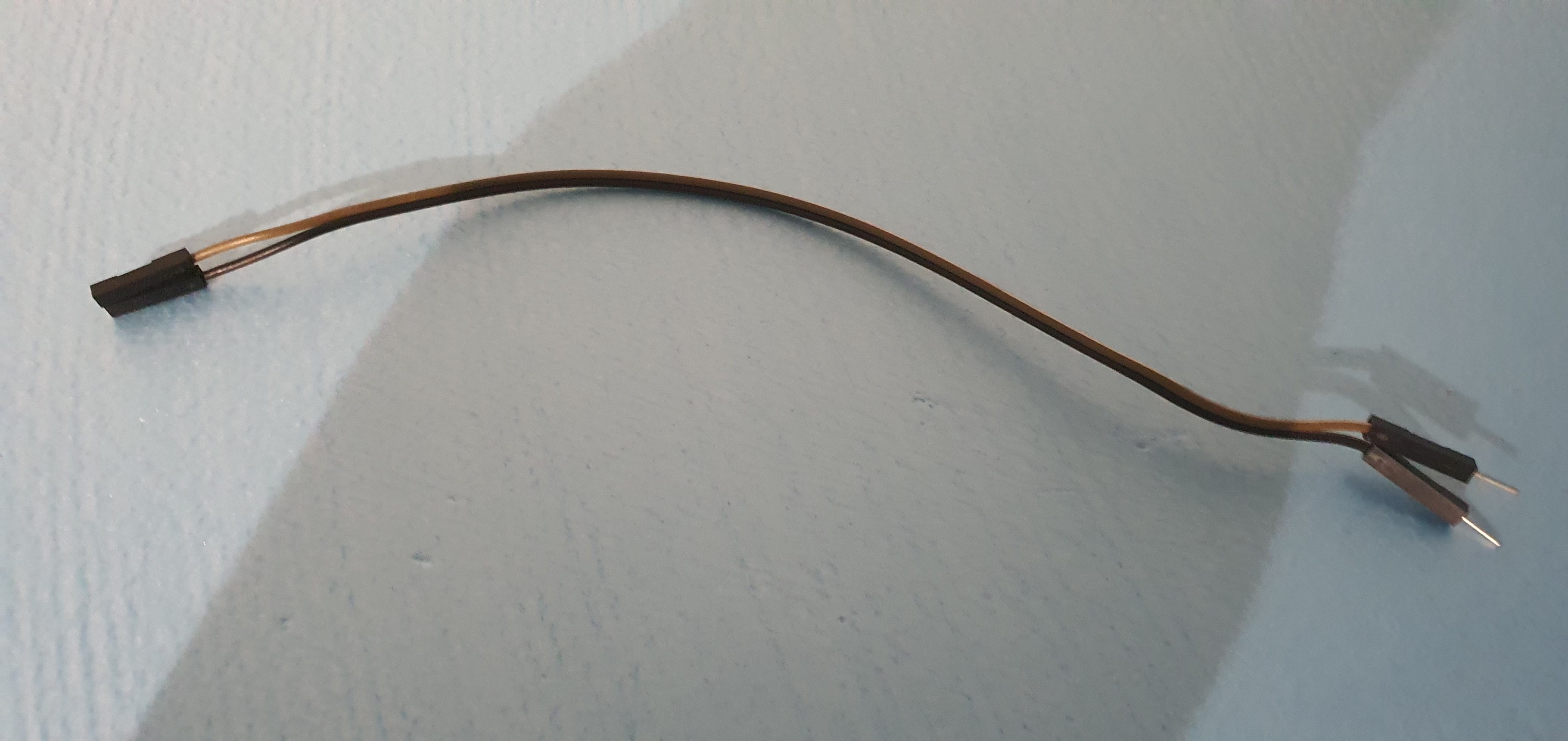
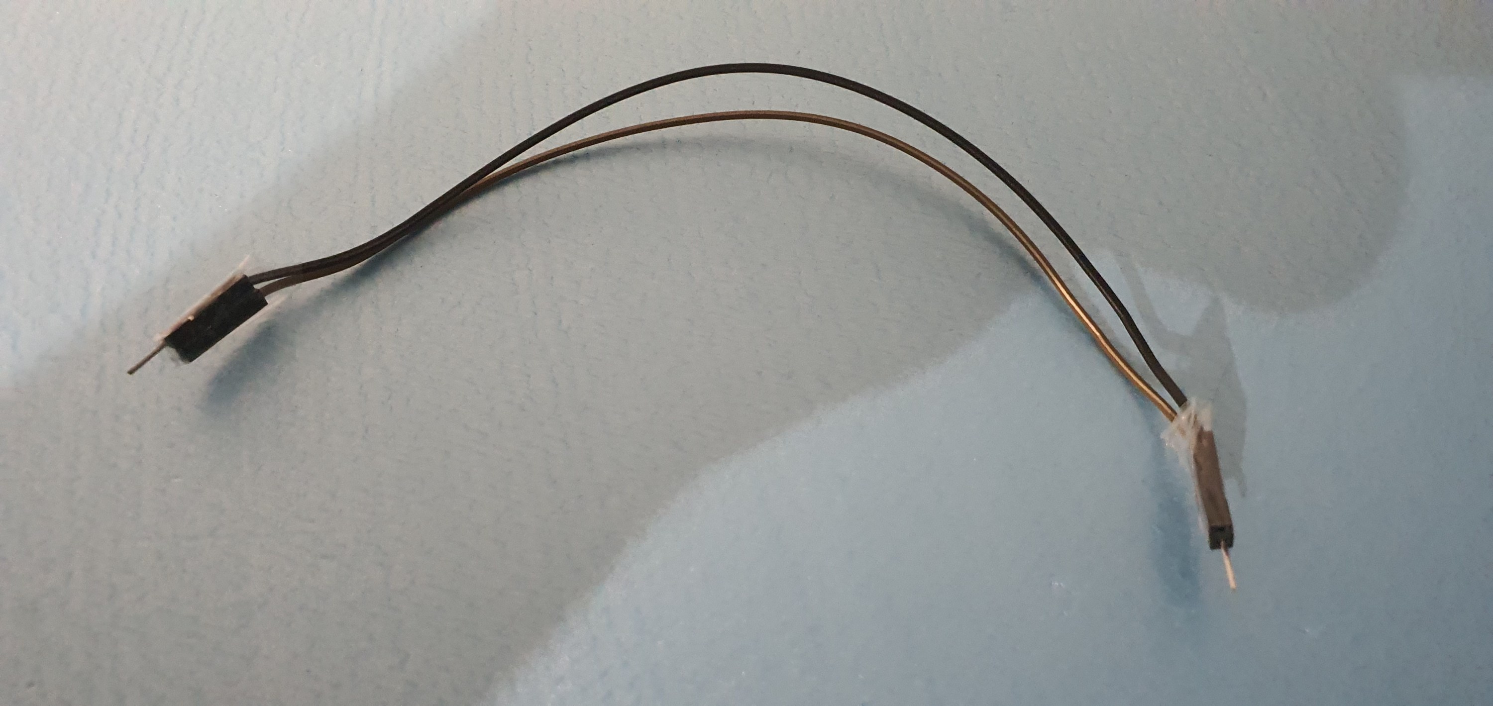
As I have said a hundred times due to our lockdown restrictions I am well down on materials and don’t have a spare power pole connector. ah! not a problem here is the poor mans solution. Take two male female hook up wires turn one around tape them together and you have a power pole connector. Lets look at how to do this.
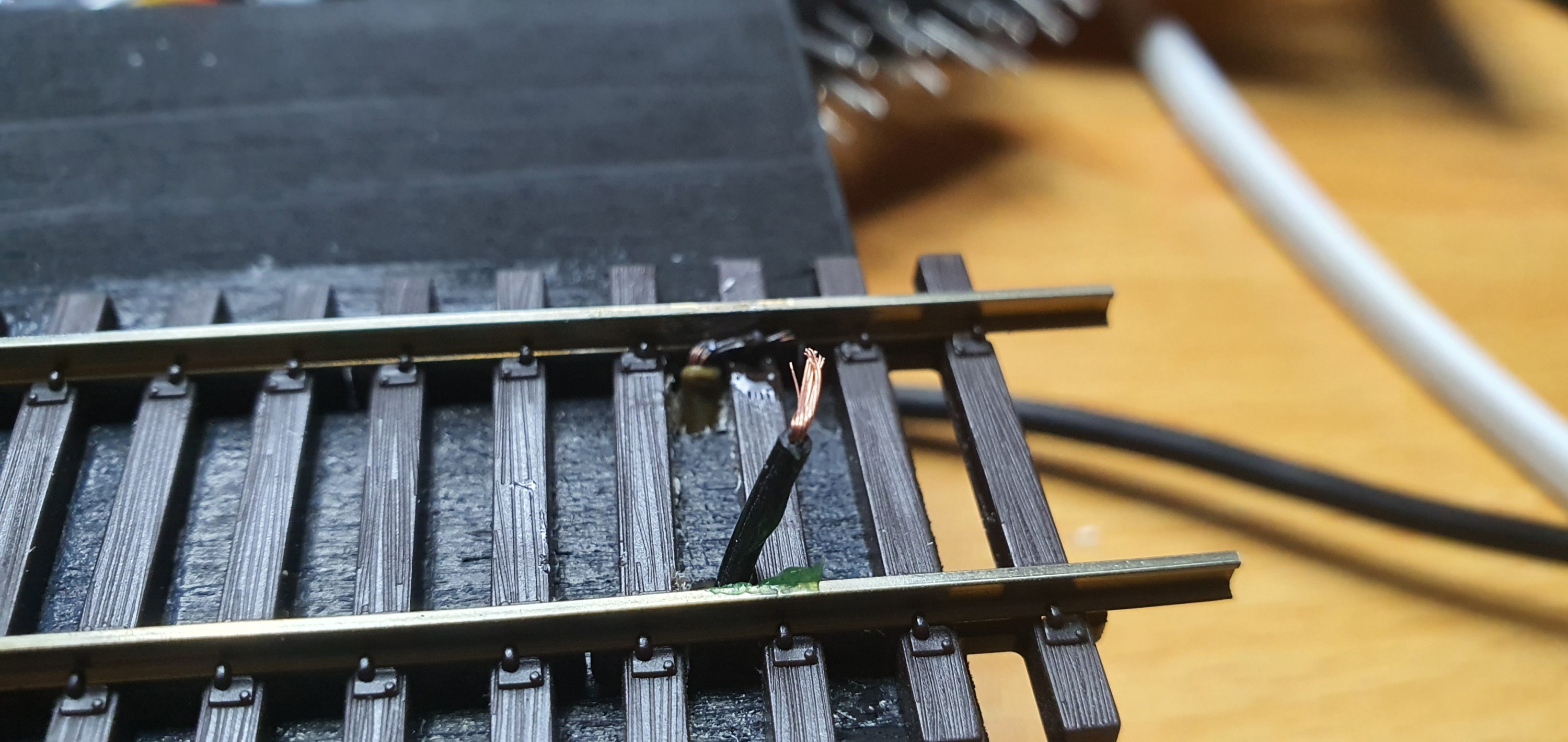
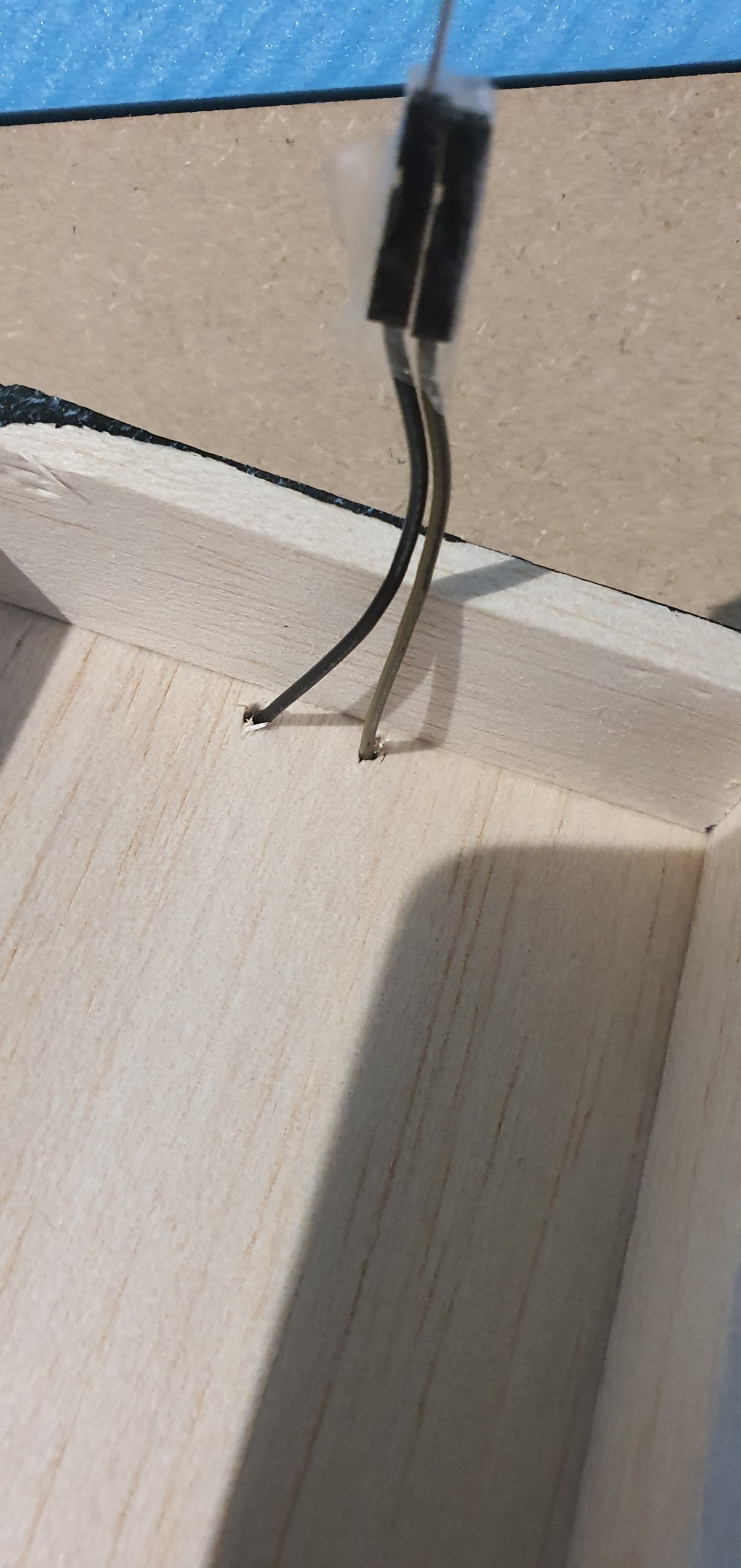
Hook up cables as they come, you get them with Ardunio sets or from AmazonTurn them around and tape the ends together cut them in half and we have two plugs for pennies – perfect eh! drill a hole for your wires to goput the wires in from below bend and tin them then solder to the inside bottom of each rail there we go one plug fitted fit the other plug to the DCC bus and we are done
A quick test
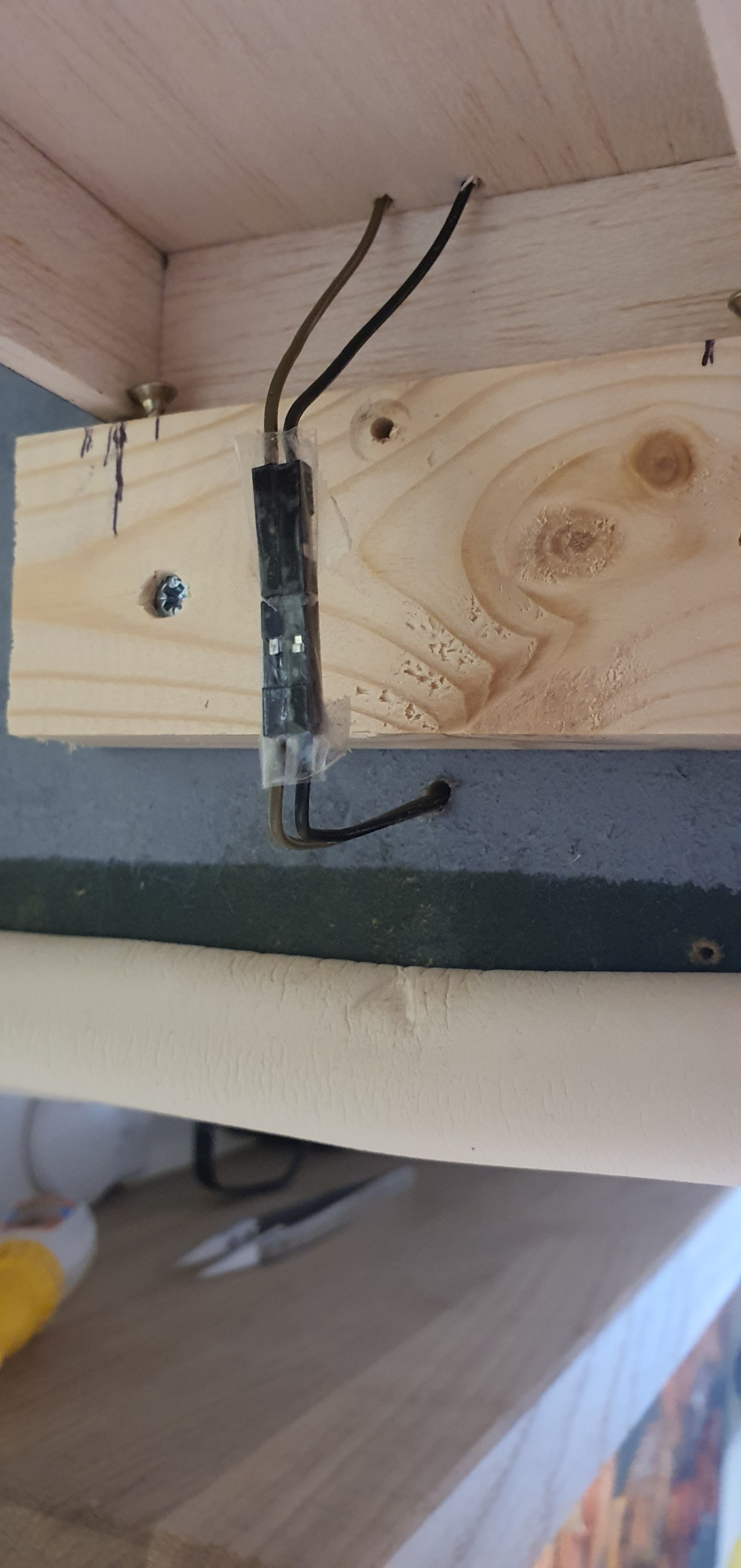
All looks good to me 🙂 storage
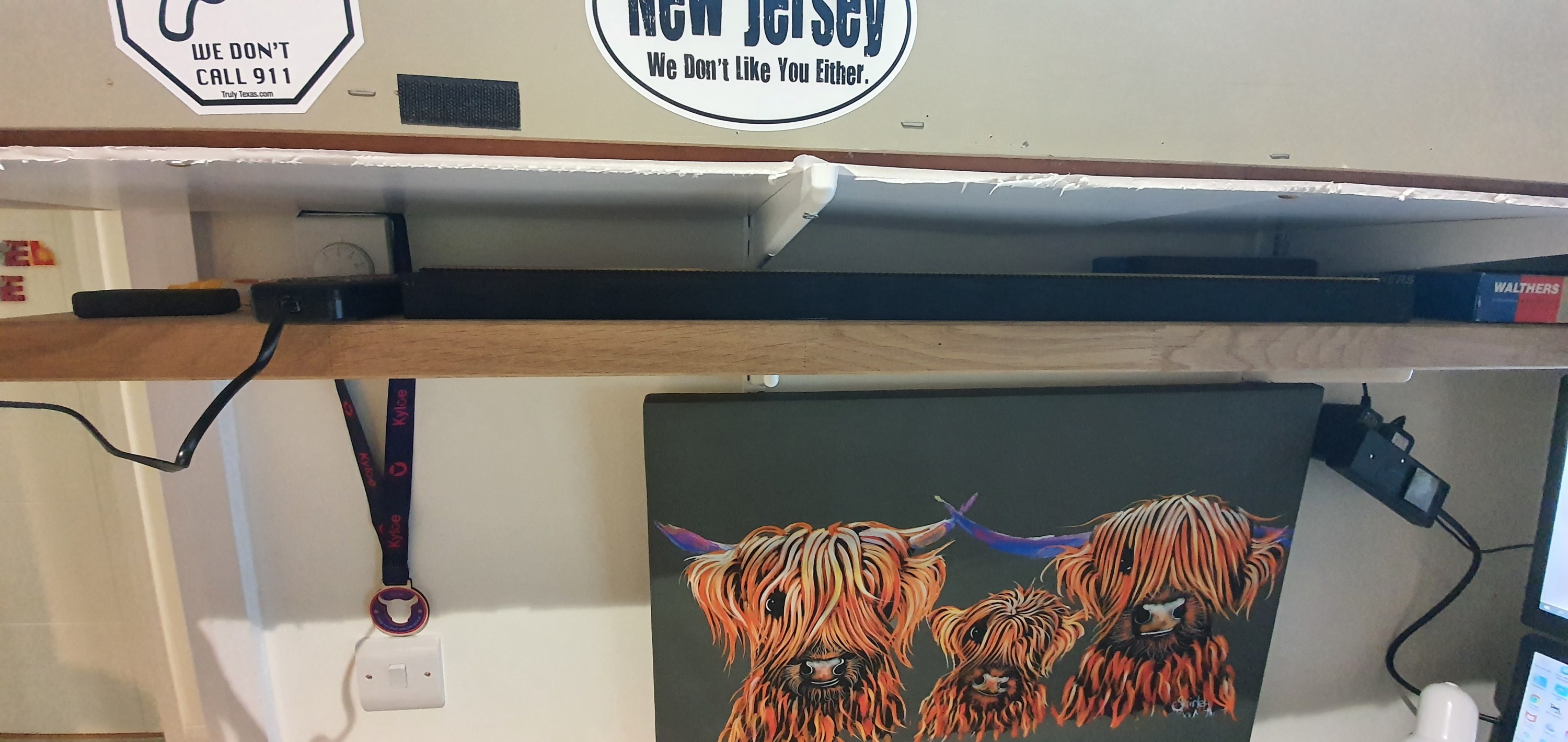
This really is a low profile solution the plank neatly fits below my layout on a small shelf that also holds some stock and the controller when not in use.
Thats it we have a working switching stick. Next up is the connection to the PC and some remote op sessions.
Now we need to add alignment screws and actaually get some track down on the staging stick.
Alignment
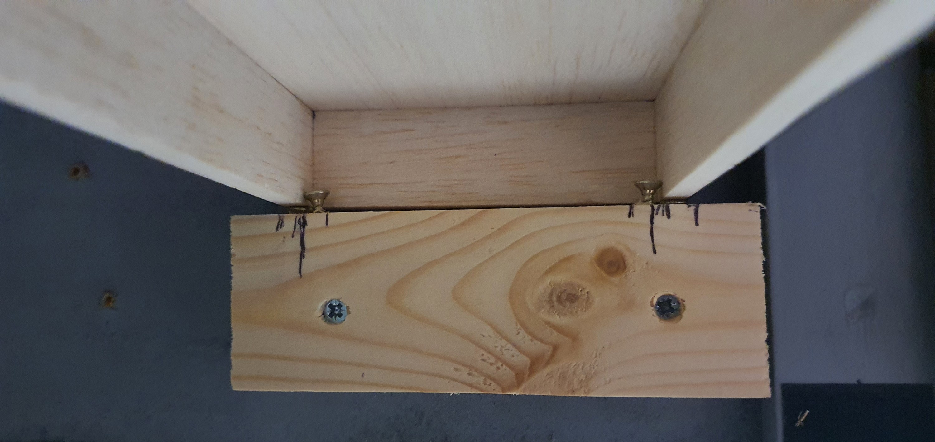
This isn’t difficult and really needed only four screws. Two of the screws are used to allow adjustment up and down of the staging plank at the layout end. This allows for the vertical alignment to be altered and adjusted as required.
You can just see them in the above image below the structure of the staging plank. The two screws inboard of the vertical alignment screws are to ensure horizontal alignment.
Fitting the track
With the track placed on the staging plank I could test the vertical alignment before applying glue to the hold the track in place.
At this point it was vital to check alignment both on and off the staging plank to so this I just used a freight car and kept adjusting the vertical alignment screws until there was no derailment in either direction or noticable movement of the car.
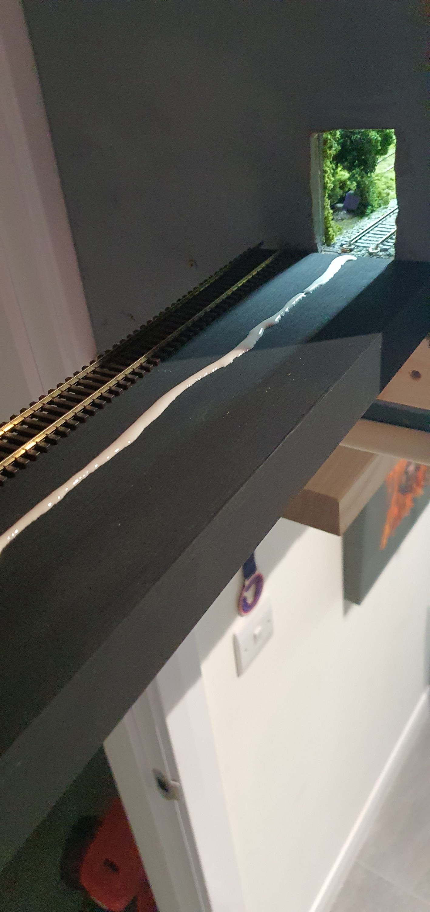
With everything appearing to run well it was time to glue the track down. This is really very simple but the basic rules of track laying apply. first lay a bead of glue along the length of the flex track not side to side, I used Gorrila PVA glue for this. Then before laying the track smooth the bead out to a flat strip of PVA glue.
Then it was time to lay the track ensuring horizontal alignment of the track and then gently pushing the ties into the glue. I like Gorrila glue because its tacky enough to hold the track in place almost immediatley but allows you to re-position some cheaper PVA glues have water added which means track will move until the glue sets so be careful. Align the track horizontally and re test before the glue dries.
Thats pretty much it you should have something that looks like this. If we were using Power onboard we would be done at this point but we are not so we’ll look at some simple electronics in Part 3 of the staging plank.
We’ll get to that in the next few days as we prepare for remote ops on the switching layout.
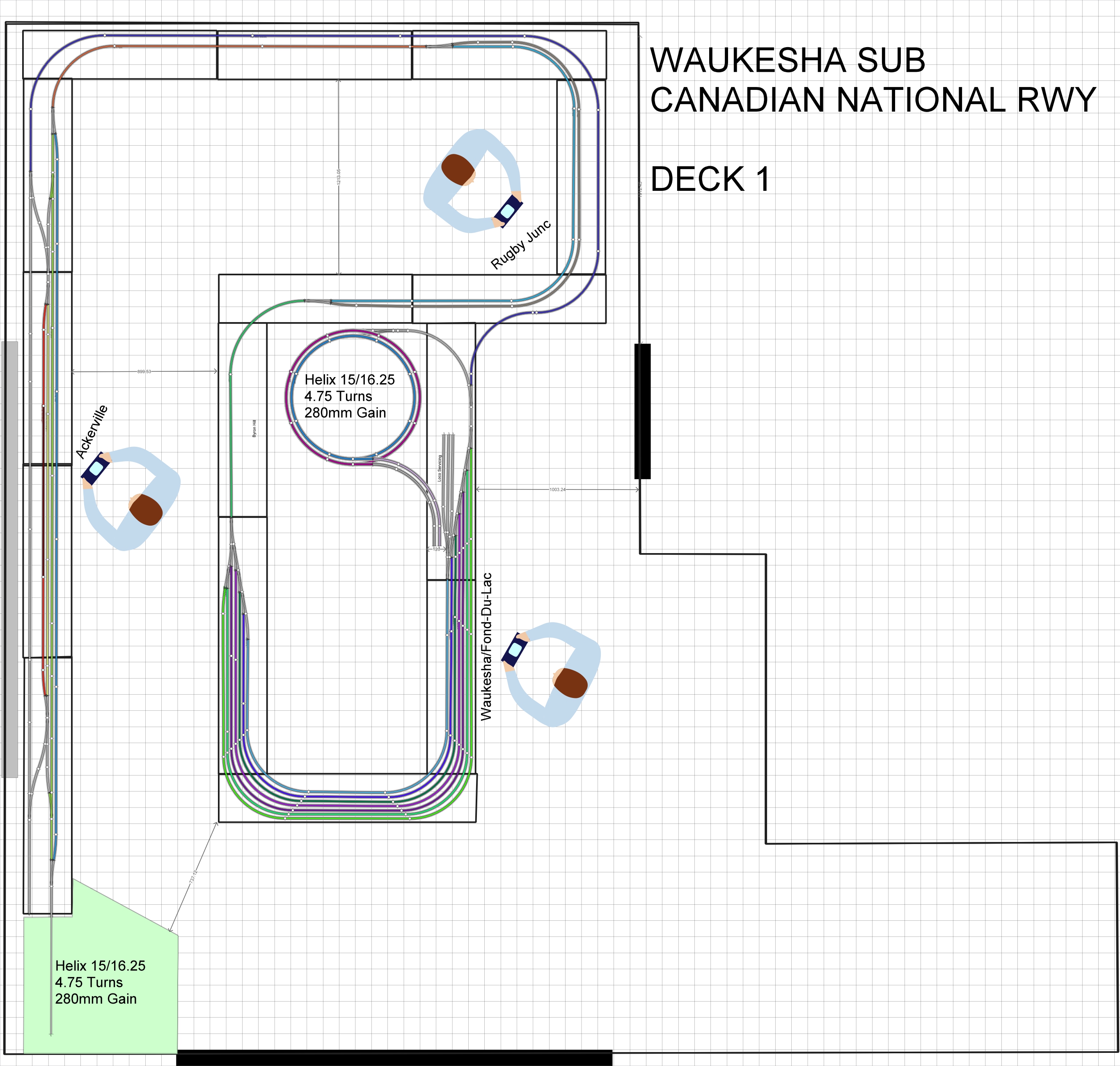
Those who use Anyrail software to design their layouts will know about a little feature called Print, which will allow you to print the trackplan in 1:1 scale. However, if like me you have a track plan covering your whole room hitting print will print the whole room including the dead space in the aisle. Thats a lot of waste so we want to try and reduce that as much as possible.
To do that we are going to take each section of the layout and copy it into its own anyrail project that won’t waste paper when we print it off.
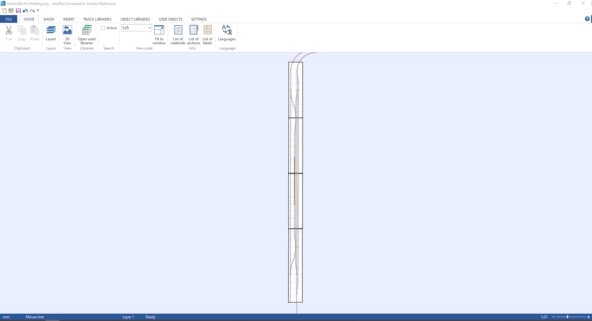
The first section we’ll do is Ackerville, thats the section on the left hand side of the track plan where the WSOR interchanges with the CN.
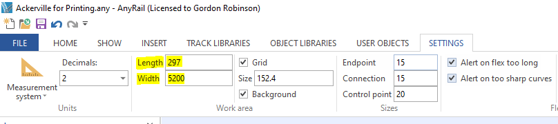
Step 1
Open a new Anyrail Project and change the work area settings to be the size of the Ackerville boards
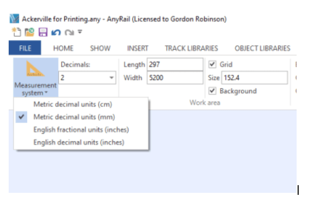
Step 2
Also make sure that both projects measurements systems are in the same unit of measure in this case Metric decimal units (mm)
Step 3
Highlight the area on the original plan that you want to copy across. Once highlighted use CTRL+C to copy the area.
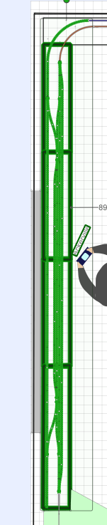
Step 4
Go over to your new project and use CTRL+P to paste the items. Line it up with your work area and then you should have something that looks like this.
Step 5
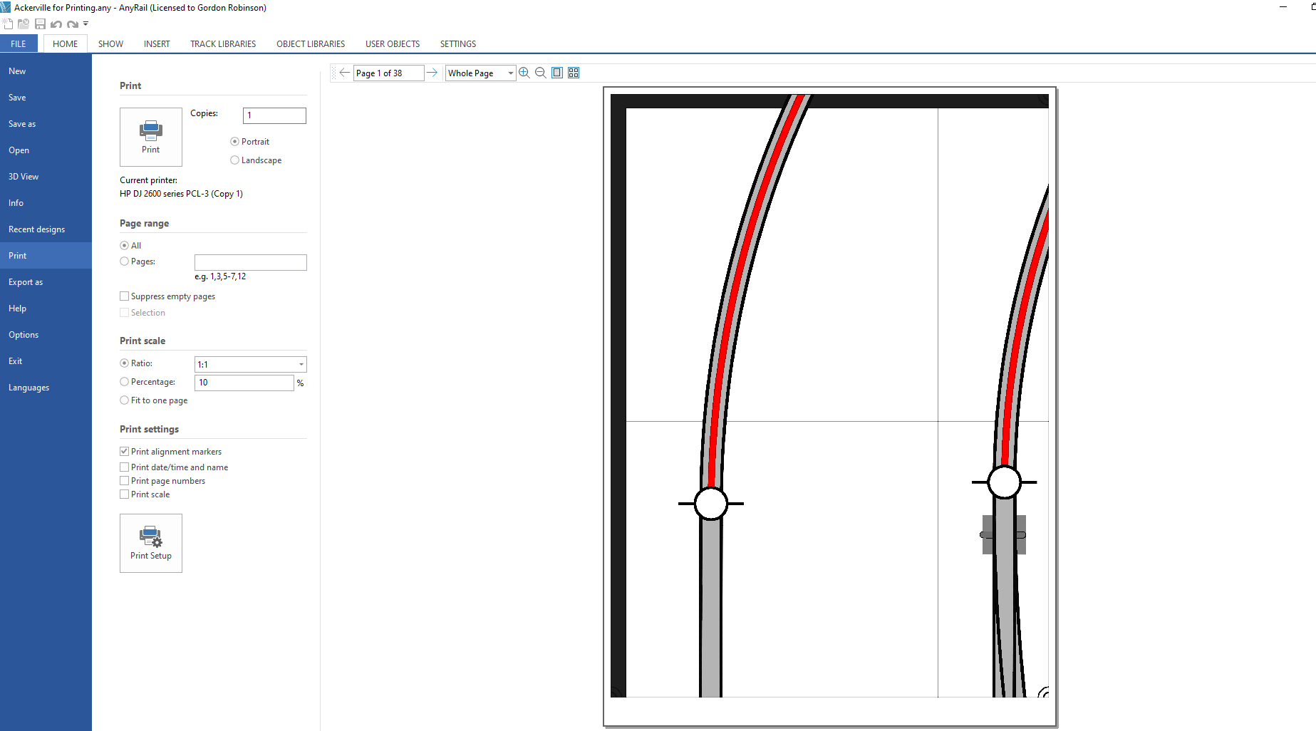
ok we are ready to print. Go to File>Print
Step 6
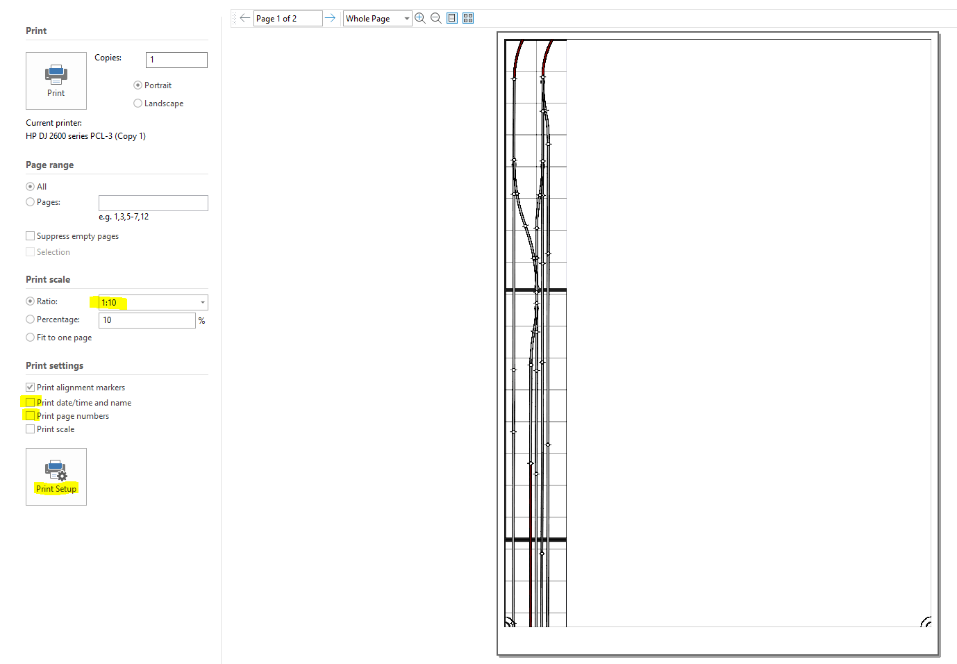
All we need to check now is the print settings.By default Anyrail is set to print off at a scale of 1:10 so you’ll need to change that to 1:1. Next uncheck the ‘Print date/time and name’ and ‘Print page numbers’ . The final thing to do is go to Print Setup and make sure that you have the size of paper in your printer selected.
Well thats it you can hit print and in my case we’ll get 38 pages that we can use to accurately mark out where the track will go and start planning scenery on this section of the layout. Printing the whole plan would have been 782 pages.
Well till next time folks hopefully we can get some time in the train room tomorrow to dismantle the layout and get those supports fitted.