More Layout Design for Jordan pt 2

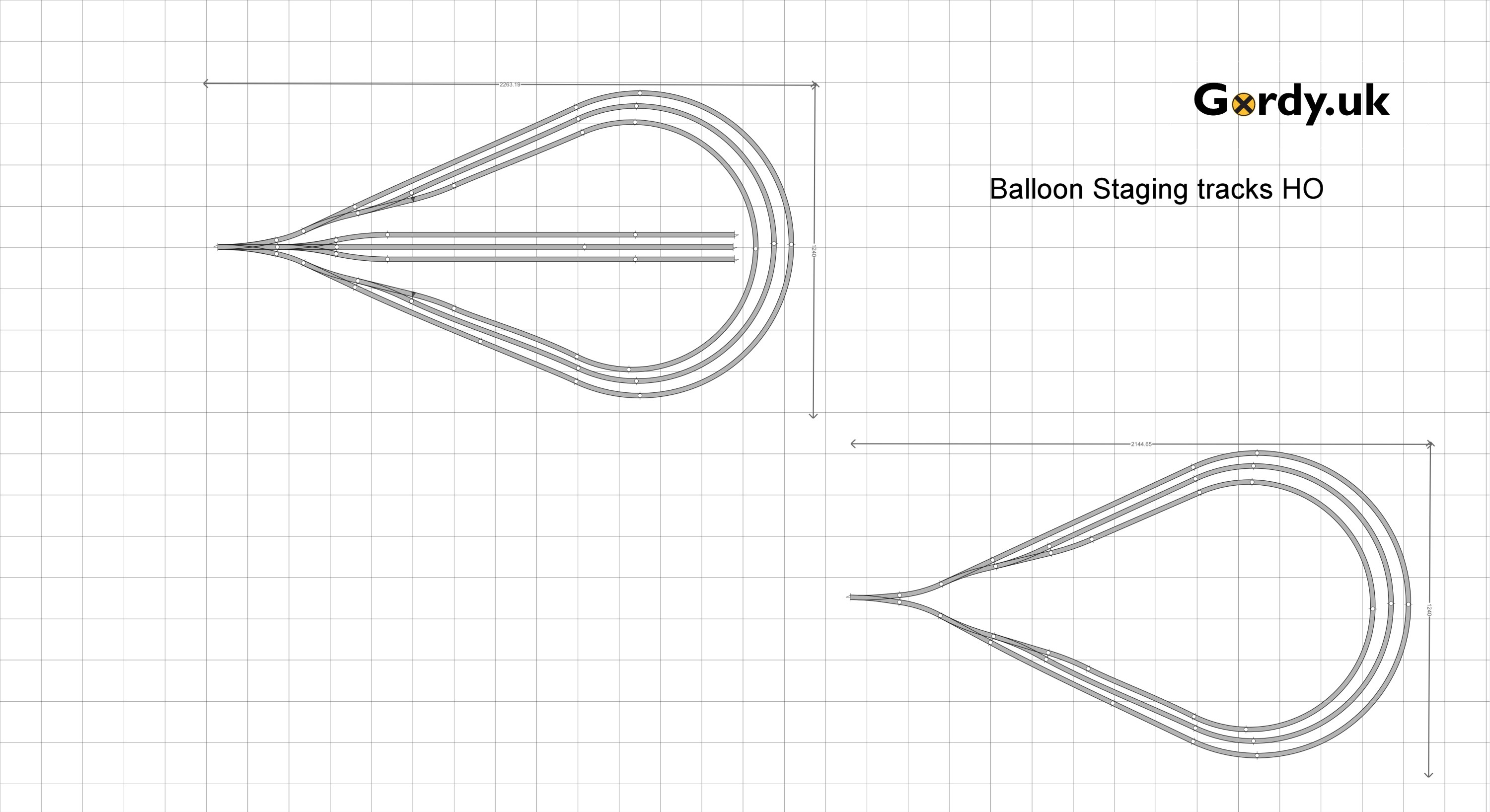
Layout Design, its like fitting a wedding dress. Death by a thousand adjustments. and so it was that Jordan came to me and asked if we could make some adjustments based on the module sizes he had choosen.

So this was how we left things last time. Jordan wanted to build the switching penisula first and so wanted to add to that design. There were other changes too as the module would now be in two sections one 36×24″ and the other 48″x24″. Jordan wanted me to include a run round and a straight section to allow a temporary staging track to be added so that the pennisula can be operated independantly.

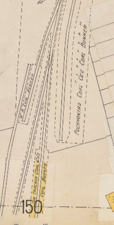
I asked Jordan to find some sandborn maps of the location he wanted to model so that we could look to add some real industries based on the prototype location. This is what he shared with me: you can find a original here

cincinnatilibrary.org

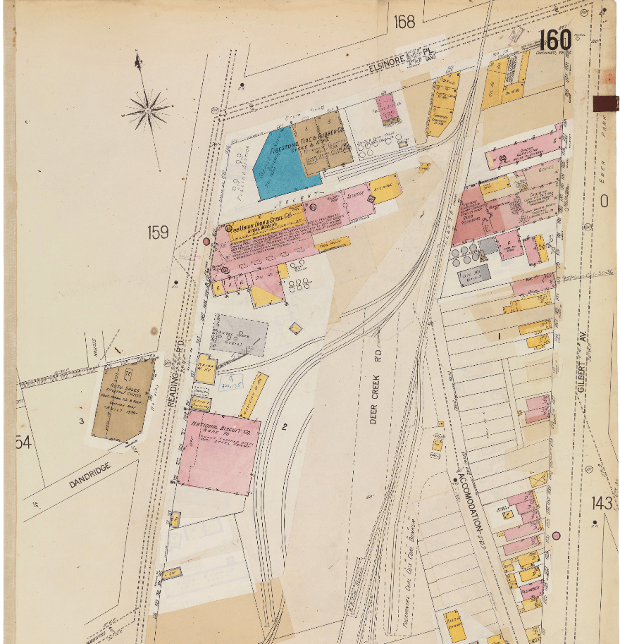
There are three industries we picked out to model. The National Biscuit Company located on the left of the map just down from the center.The Gas Station which was rail served located on Elsinore Place at the top centre of the map. Then finally the coal drops or as they are called on the map ‘bunkers’ which belong to two seperate companies.

We are not aiming for a perfect representation of the prototype location here so lets look at the industries we modeled in real life and on the layout design.

National Biscuit from the Sandborn Map
o

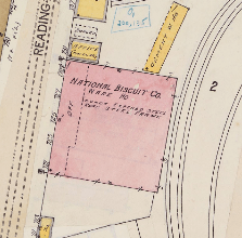
On the layout we had to model National Biscuit as a background flat. When the layout is used stand alone the second track in front of the main loading/unloading track for National Biscuit isn’t used as car spots but in the future when the whole plan is built it can be. Thus this industry doesn;t take up alot of space but does give 4/5 car spots.

Iron Oil on the Sandborn Map at 621, Elsinore Place, Cincinatti

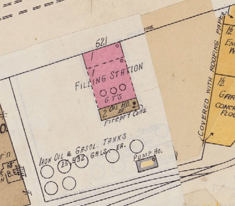
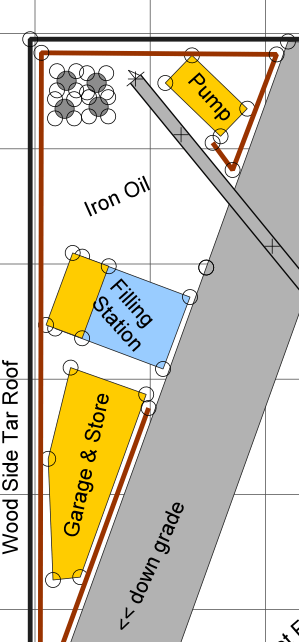
So on the layout Iron Oil occupies the corner and includes a Gas station and the store & workshop buildings seen on the sandborn map. The track crosses the street though to serve the oil storage tanks at the rear of the lot. This should add a single spot for a tank car with the crew having to flag the crossing of the street slowing down operations.

OK finally lets look at those coal trestles, a signature feature of any 1920’s city where most heating and cooking would be from coal fires, even in apartment buildings.

Pocahontas Coal Co & The Thacker Coal Company Coal Bunkers

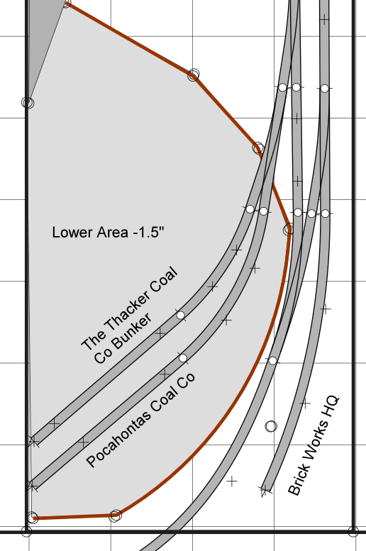
On the layout we’ve been able to model both trestles but side by side. The area around them will need to be lowered so a retaining wall will be added (shown in red) to enhance the scene. It will be upto Jordan to decide if this wall is brick or stone. So more research needed to dig out some photographs to help with planning the scenery before construction can commence.

Finally we added a vacant lot and also a place for the Brick Works downtown unloading area . The vacant lot to help set the scene in 1920 when the city was still mostly under construction and the Brickworks to add another three car spots. If the Brickworks is omitted in the first iteration of the plan it will give Jordan somewhere to store his train between sessions and he wouldn’t need the switching stick.

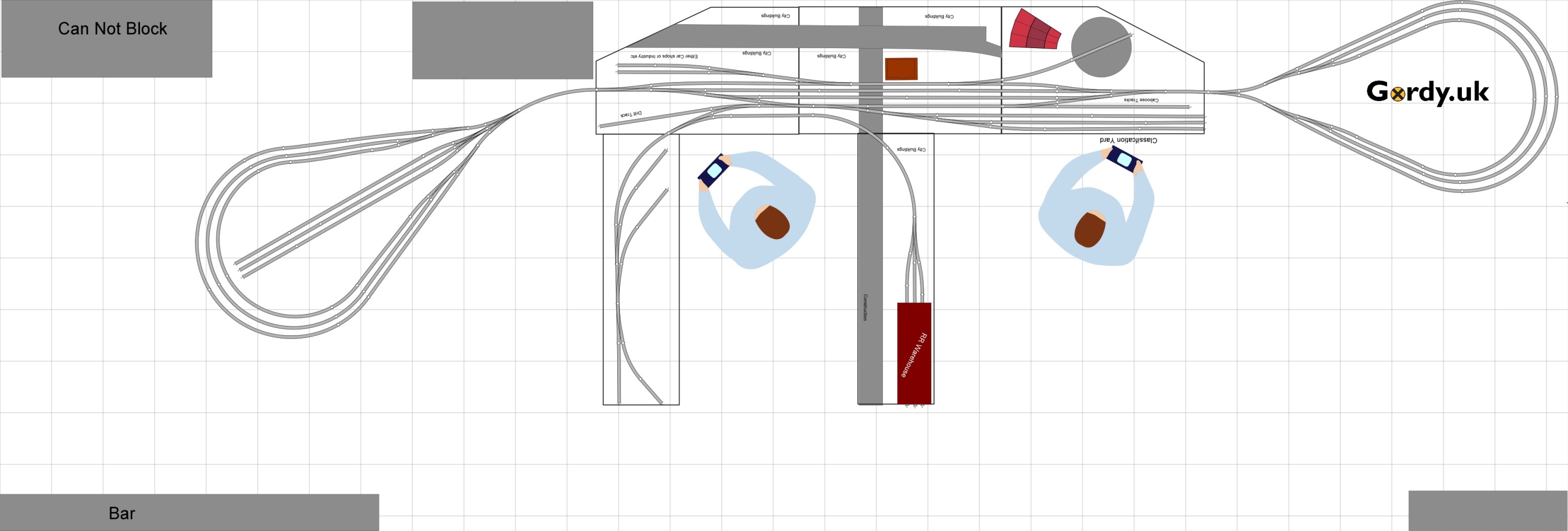
Right well lets look at the overall plan for this section of the layout now.

Pretty cool eh! well we also designed another part of the layout in more detail but that can wait for a future post. Hopefully the postie has brought me more materials and we can crack on with the Waukesha Sub in the coming weeks.

Amherst (Springfield) Virtual Train Show 30-31.01.2021

Well this weekend we should have had the largest train show in North America at the Eastern Exposition Center in West Springfield MA.. However thats just not possible with the current restictions in place. I have been lucky enough to attend the show in 2018, 2019 and 2020. Infact it was my only train show in 2020 so I was very fortunate.

The folks at the show and the vendors have worked with Virtual Railfan to put on a virtual train show today and tomorrow. I reccomend tuning in even if you haven’t or never will be able to attend the real show in person.

For more information visit https://virtualrailfan.com/amherst/

Waukesha Sub Division: Ackerville Scenery Base continued…

Yesterday you saw how i got the foam blocks in place that would support the WSOR mainline. Big square blocks don’t really conform to nature so I will need to add the embankment slope.

To do that I used a hot wire foam cutter to take about a 45 degree angle from the base to the top of the sides of each foam block.

I didn’t try to be too even as one its really hard to do free hand along a 4ft length of foam and his whole area will get covered in sculptamold before any scenery goes down here.

Carrying on from the first image in this one you can see that the profile has been cut into both sides of the foam block to form the embankment.

At the southern end of the yard I added a 2% grade, this is just for variety really but there are full trains that will need to negotiate this incline to access the WSOR Milwaukee sub during op sessions so I wanted the slope to be more gentle as this will be more than just dropping a few cars into or out of the yard as at the Northern End. In real life because of the grade crossing just north of the yard most switching and interchange is done at this southern end.

The raised WSOR mainline continues around the corner onto the next section of modules before the grade brings it down to level again with the CN before Rugby Junction. The highway overpass will cross the module about level with the leg seen to the left of the picture.

So now we await the arrival of a few bags of sculptamold and we will get this scene progressed.

Here finally is a complete overview of Ackerville with its base foam just placed onto the module tops. This will be a signature scene on the layout I am lucky to have such a long aisle in which to place it. Crews here will have plenty of room to complete their work.

Well its Friday so grab yoursleves a wobby pop or soft beverage of your choice and head back to your workbenches.

Waukesha Sub Division: Ackerville Scenery Base

In a follow on from tuesdays post, which you can read here its time to put some scenery base in for the Ackerville scene. This is the rough building blocks that will be used to for lanscape features to support track, roads and structures.

I started by slicing 70-80mm strips of 20mm foam to use for the WSOR mainline which is elevated above the rest of the yard.

These square blocks were then place roughly in position with the turnouts at the yards Northern end.

To get from the WSOR mainline into the yard I cut section of foam with a grade of 4% to drop the main from 20mm to 0mm height in 500mm. A small inset section was cut into the 20mm thick foam to allow the two sections of foam to come together.

Here is a side view showing the incline and height of the WSOR above the yard and CN main. It looks quite high but based on the images I found the line is about one fright cars height above so this is actually a little lower than reality but 20mm feels right and we are already compressing the scene so perspective is important.

The foam does’t go all the way to the backscene so that there can be fall away before the tree line as it is in real life. I kept adding foam blocks until I reached the Southern end of the yard.

The next job will be cutting the slope of the embankment into both sides of the foam blocks join us tomorrow to see how that comes out.

NMRAx January 23 2021

Well we have been doing these events now for 9 months and they just keep getting better. I am glad there is such a good team running these events which just wouldn’t happen without Brac, Martyn, Speed, Andy, John & Brooks and our cast of clinicians. If you missed the live shows you can still watch them on Youtube.

The Schedule for the event was:

To watch part one go here:

To watch part 2 go here:

Waukesha Sub Division: Ackerville Scenery Planning

Ackerville has to be one of my favourite places on the Waukesha Sub Division so it had to be included in my layout. Its a small interchange yard between the Wisconsin & Southern Railroad (WSOR) Milwaukee Sub Division and the Canadian National (CN) Waukesha Sub Division.

Source openrailwaymap.org

The area in red what will actually be included on the layout. Plans like this are great for trackplanning but pretty rubbish for planning the composition of the scene so we need a photo or ideally a series and the internet is a great source.

Ackerville, Wisconsin
https://www.flickr.com/photos/siouxline/42352478470/

This overall view, taken from Slinger road looking south, shows that we have a nice scene boxed in from the front and rear by a tree line. Other than some lineside equipment boxes the only other structures are a communications mast and a highway overpass. As we look at this photo the left hand track is the WSOR Milwaukee Sub Division and the CN is on the right. The left hand tree line will be our backscene and the right hand tree line will be removed as it will be the edge of the layout and we want to be able to see our trains.

Whilst an overhead shot is really nice to have, what we need to see ground level elevation is a shot taken from ground level. So back to the internet to see what we can find.

WSOR L249 at Ackerville
https://flic.kr/p/2hmiMVx

This photo of WSOR local L249 working the yard shows that whilst most of the forground is flat the WSOR mainline to the rear is actually elevated with two sharp grades used to access the yard. You can see how the tree line dominates from behind the WSOR embankment and will make a fantastic background.

Now this images is in summer and because I am totally colour blind I have decided to set my Layout in January. Therefore we need snow lots of snow so lets try and find a picture of Ackerville in Winter.

Ackerville In The Morning
https://www.flickr.com/photos/firstlight55/40044975924/in/pool-trainmeets

Its a WSOR take over, well not quite here you see CN local L510 working the yard with an exEJ&E locomotive still in original paint tied down in the yard. As that local which runs from Fond-du-lac to Waukesha as a turn, i.e. it comes back, is paused the T004 Horicon to Janesville WSOR transfer exercises its trackage rights between Slinger & Grand Ave Waukesha. Hopefully we’ll soon be recreating this ourselves soon in on our own minature version of this busy section of mainline.

Things to note for the scenery are the switch stands in the yard and the tyre tracks from MOW trucks at the side of the CN mainline. Its little details like those that make all the difference.

Join us on Thursday as I start to cut some foam and make a start on laying out the scenery base for Ackerville.

Waukesha Sub Division: Backscene and upper deck supports: Part 2

We previously looked at modifying the Elfa twin slot uprights to add an additional screw hole so that we can use them to support the upper deck, back scenes and eventually the lighting for the layout. The uprights will be fitted at 600mm intervals meaning i need 33 in total. However I was only able to get 11 of these from my supplier, I am hoping to get the remaining 22 shipped to Orkney by the end of this week.

modified upright next to a unmodified upright

With only a limited number of uprights it made sense to work on the hardest to reach areas first. this means working in the area marked in red on the plan below. As the layout is modular i was able to remove the left hand 4 modules of the layout and the intermediate module on the right hand side before moving the whole section againse the wall out to enable access to the rear. If you were not concerned about damage to the wall of course you could just ignore my step and screw the uprights straight to your wall.

So lets get on with getting these things fitted.

I levelled up the base of the upright with the base of the module and marked the hole for the upper screw. being sure to ensure that the screw would be going into the cross support of the module and not hitting any of the brad nails used during the modules construction.

Then I used 3.5mm x 30mm screws to secure the upright.

Using the top of the module I squared the upright to be vertical and then ran in a 5x60mm decking screw (mainly because i had them on hand) into the lower hole securing everything square. These are probably over kill but this should prevent the uprights from moving when under load.

Here you can see what the uprights look like in place on the module I removed to allow the large rear section to swing away from the wall. it certainly was alot easier to do this module than the others.

Here you can see the completed view of all 11 uprights in position. There are above my workshop area and over the coming weeks I’ll be adding the back sceneswhich will permantently take away my ability to take these overall shots.

In these two shots taken whilst the modules were detached you can see the brackets for the second deck and eventually the lighting rig. The second deck supports are 120mm long which will enable a small shadow box effect above the lower deck. The upper supports are 320mm and will extend just in front of the lower module deck supporting lighting for both decks and completing the shadow box look.

Look out for tomorrows post where we will look at scenery planning on the Ackerville section of deck one.

New Model Railroad Podcast Alert!!!

Well its not everyday that we get a new podcast especially from an NMRA division but the Twin Cities guys and girls have done it. The division is based in MSP or the Twin Cities to those in the 🇺🇲.

The effort led by Thomas Gasior MMR released its first episode on Friday Jan 22 2021. The first episode talks about using car cards and waybills for model railroad operations helping your cars move with purpose on your model railroad.

You can subscribe to the podcast or listen to their first episode here https://podcasts.apple.com/us/podcast/the-crossing-gate-twin-cities-division-of-the-nmra/id1549943658

Happy Modelling, Gordy

Remote Dispatching (operations) from Orkney to Texas an Introduction

For the past 6 months I have been logging hours towards my Chief Dispatcher AP certifcate which is part of the NMRA AP program. https://nmra.org/chief-dispatcher

The requirements are two fold, actual operation of a model railroad in different roles (engineer, dispatcher, traffic controller etc) and then a write up on how the operating scheme was developed with reference to prototype practice. Back in July 2020 I helped develop such a system for Gert Muller’s TxNamib layout in Dallas Tx. The N Scale multi-deck layout in a 20x20ft room depicts the railroads of Namibia but using US locomotives and rolling stock that would be seen in Texas.

Operating sessions are from 6pm-10pm on Wednesdays, yes thats midnight to 4am here in Orkney but its worth it. The layout doesn’t yet have signalling and is all single track mainline with the exception of the Helix. So the system developed for operating is based on Track Warrants althought there are still dispatch panels and the dispatcher controls all mainline switches. The system uses the free google documents software, with google forms used to produce the track warrent which is copied down on paper by the conductor in Texas. The data from each track warrant outputs to a PDF in Google Drive which is visible to the Conductors if required and also to a Google Sheet that logs the data from each warrant and is also where the dispatcher log sheet is completed during a session.

I may well cover the creation of these electronic/paper lite versions of operating paperwork in future blog posts if there is interest.

The next thing that we need for this craziness is a way to communicate. I found that we could use a free app called Zello for this. It allows uses to create a network of connected devices into a channel. A really cool feature is that you can create multiple channels and pop them out over other apps on your device so you could have a channel to dispatch and another to your conductor and then you can overlay a push to talk (ptt) button over the top of apps such as Engine Driver to talk and drive at the same time.

We realised that the dispatcher can get lonely when things happen and you are not in the room or there is a lull in activity during a session so we use a video conferencing app to allow the superintendent AKA Gert “Speed” Muller to communicate with the dispatcher.

Its all worked so well that I have now logged nearly 30 hours on the railroad and have trained other dispatchers who need to log hours for their AP certificate to run the railroad. Its been a great experience, we’ll cover some of the paperwork used to remotely dispatch and the paperwork for the AP certifcation submission in next weeks blog posts.

To read more about speeds layout check out www.txnamib.com

Helping out with track planning & Layout Design

I have a friend Jordan in Ohio who is always planning new freemo modules or layouts and on Monday he asked me to help him with his track plan for a basement layout.

A quick run down of his requirements were:

Must haves:

  • set circa 1920
  • 10-12 car trains
  • Has to be modular no longer than 5ft modules
  • needs to go against a wall but access at each end is required.

Nice to haves:

  • Urban scene
  • Must be able to pass two trains
  • Classification Yard
  • Some Industries to include LCL
  • Roundhouse/loco servicing
  • 2/3 crews but could be operated by one person.
  • House track in front of the Depot (its 1920’s they ran Passenger Cars)

I love drawing track plans and layout design and I often help folks out with their plans. With Jordan being in Ohio and myself in the UK we used some video conferencing software and shared my AnyRail screen so we could discuss the plan together as we went. To be honest he watch a youtube video on Dave Abeles Onganda Cutoff but hey thats how it goes.

What we eventually came up with was a small yard buried in the inner city jungle of 1920’s Ohio which tall buildings forming urban canyons and view blocks. The yard has a 19 car capacity and two pennisulars provide local switching work for the yard, including a LCL Railroad Warehouse.

On the otherside of the yard is a small roundhouse and space for either a car repair shops or an REA or other warehouse in the urban part of the layout. The layout can either be operated with staging yards or part of a Freemo set up or even on its own as a small switching layout.

100mm Grid all turnouts Peco #8 and two curved #7

So now we need some staging, I suggested to Jordan that two Balloon style reversing loops one with stub ended staging in the middle would work best for him as they can be made using 4×8 sheets of ply.

Ah ha! We are making progress so lets see this thing finally fitted into the space that Jordan has. Of course it does and its obvious this is going to be a really fun layout to run. The grey areas are places that can’t be covered or blocked but we have avoided those and there is still plenty of space in the room for entertaining.

Well its the start of another weekend so lets get back to the workbench.