So having built the turnouts for the Norwalk Valley RR, i have no worries about scratch building a turnout but now i have to build at least two over types of track work.
Turnout
So first the turnout. I used a No5 turnout assembly fixture to construct my turnout. I also did it at Leigh Model Railway Show, while demonstrating at the side of the Norwalk Valley RR.
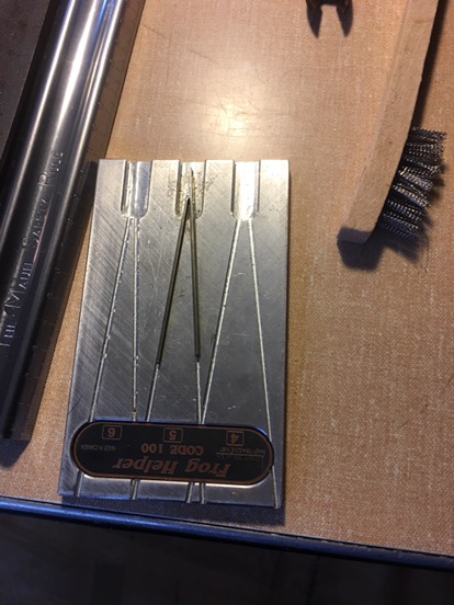
forming the No5 frog
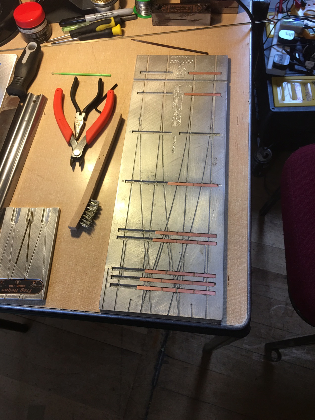
laying out the ties
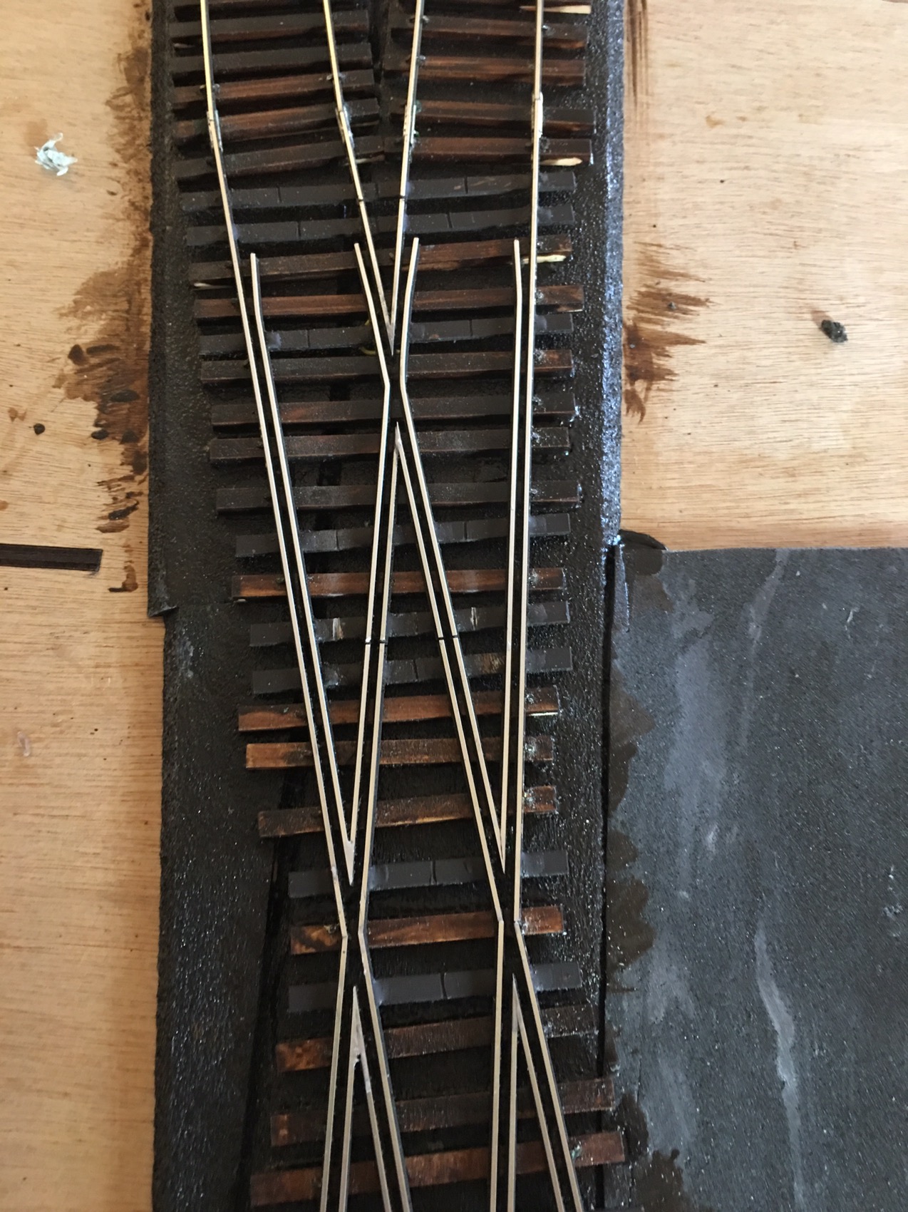
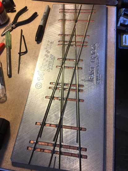
14 degree crossing
So alot more complex than a turnout and with alot more angles. Well angles everywhere to be honest, unfortunatley i didn’t take pictures until i was 70% of the way through, honestly i was concentrating too hard on making cuts in the right place and getting my angles correct.

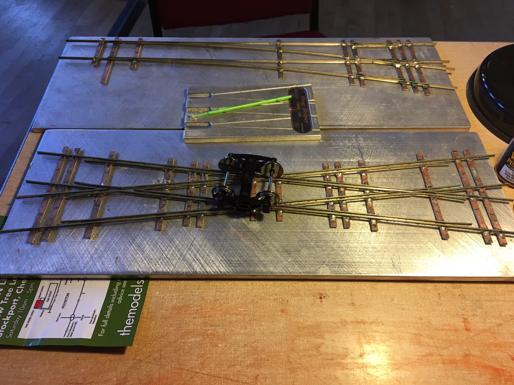
14 deg crossing by #5 turnout for comparison
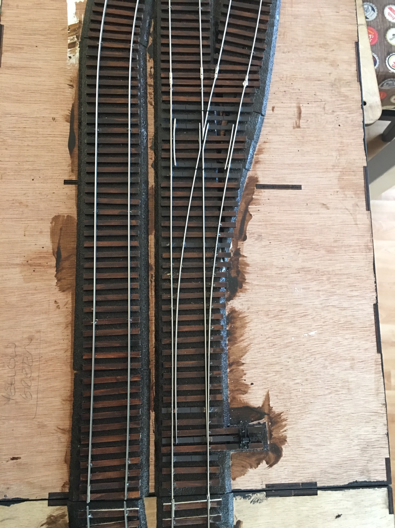
Single No5 Crossover
So as i have the assembly fixture i have decided to attempt to use it to help built a crossover but i know that there will need to be some extended check rails for it to be a crossover rather than two turnouts so watch this space this could be the most difficult track feature i scratch build yet.
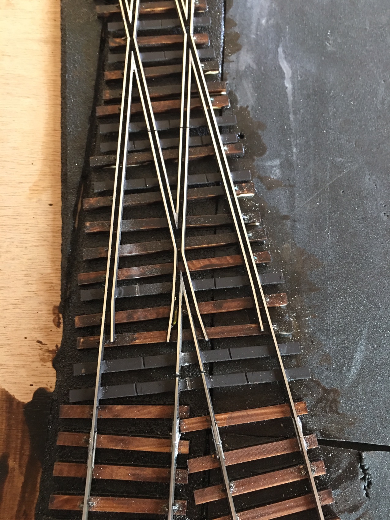
So today i finished my number 5 crossover it was a challenge and has take about 5hours to construct but well worth it. I am just fixing down the ties for it.
Next steps for all my trackwork will be painting then fitting to the sleepers and finally wiring.
Presentation Piece
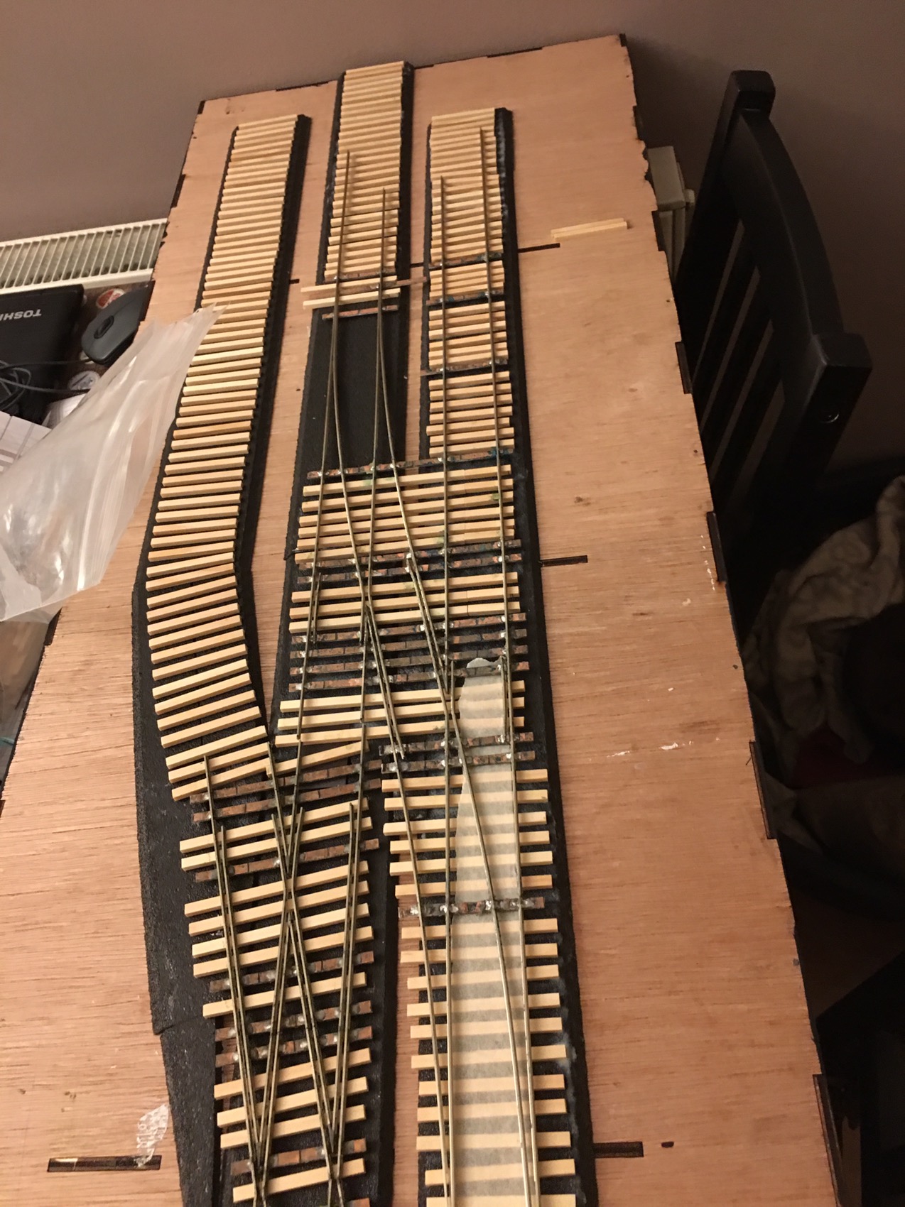
All apprentices had to do an apprentice piece and i am doing just that to display my track work. Its not required for the AP award but i hate building these and not using them. So i have built a very small portable O scale layout using these track items and a few more. It will be 100% hand laid track and will allow me to tick off some work for sections of other AP awards.
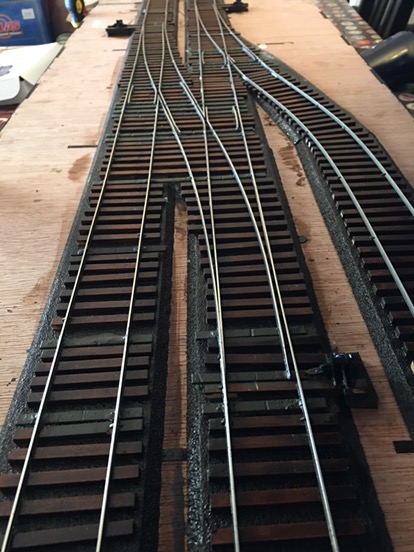
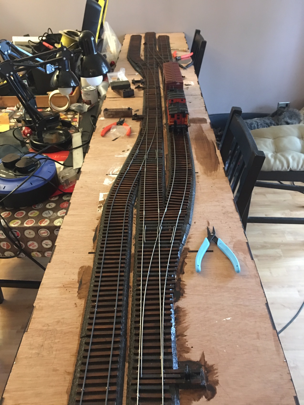
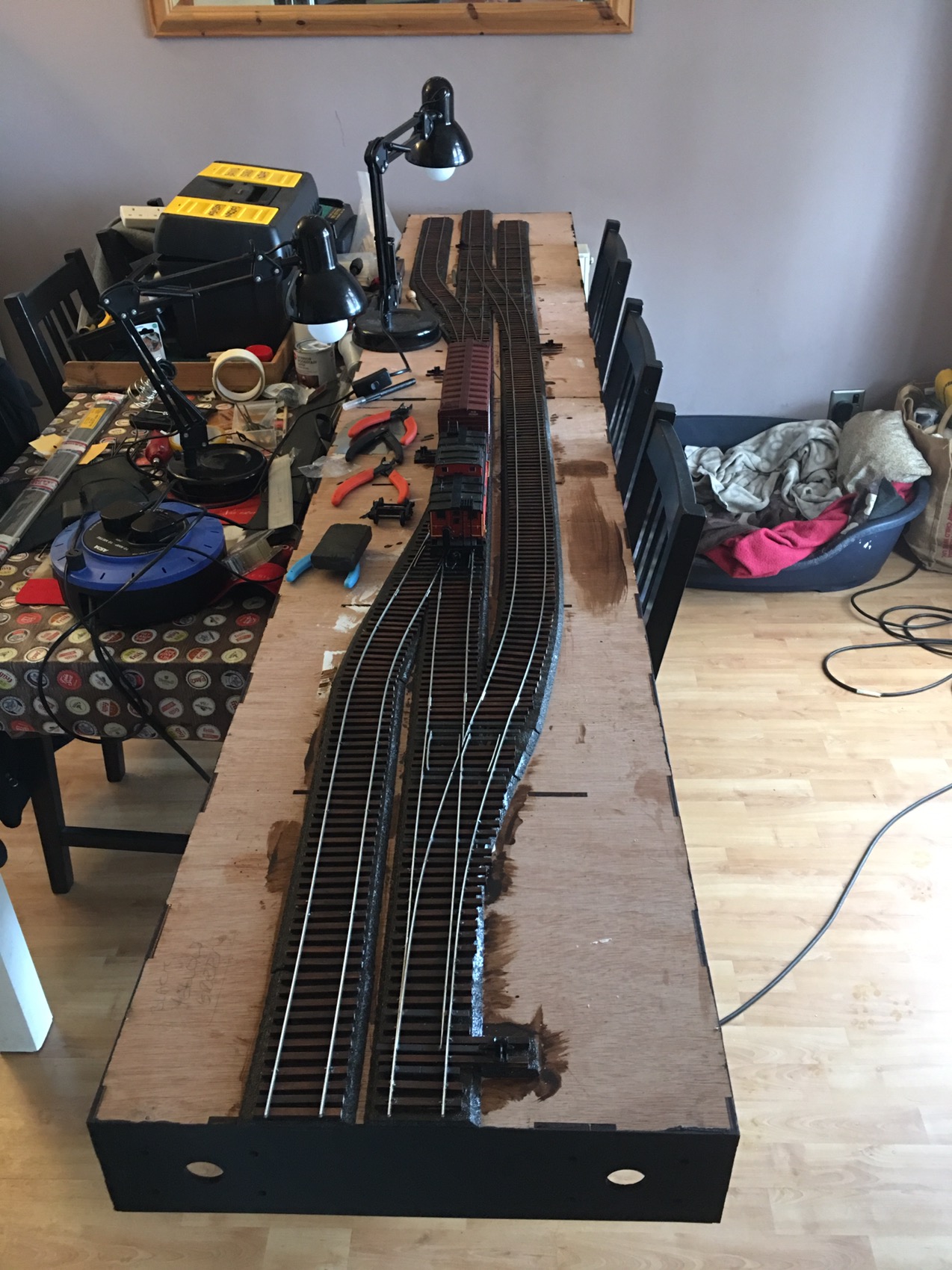
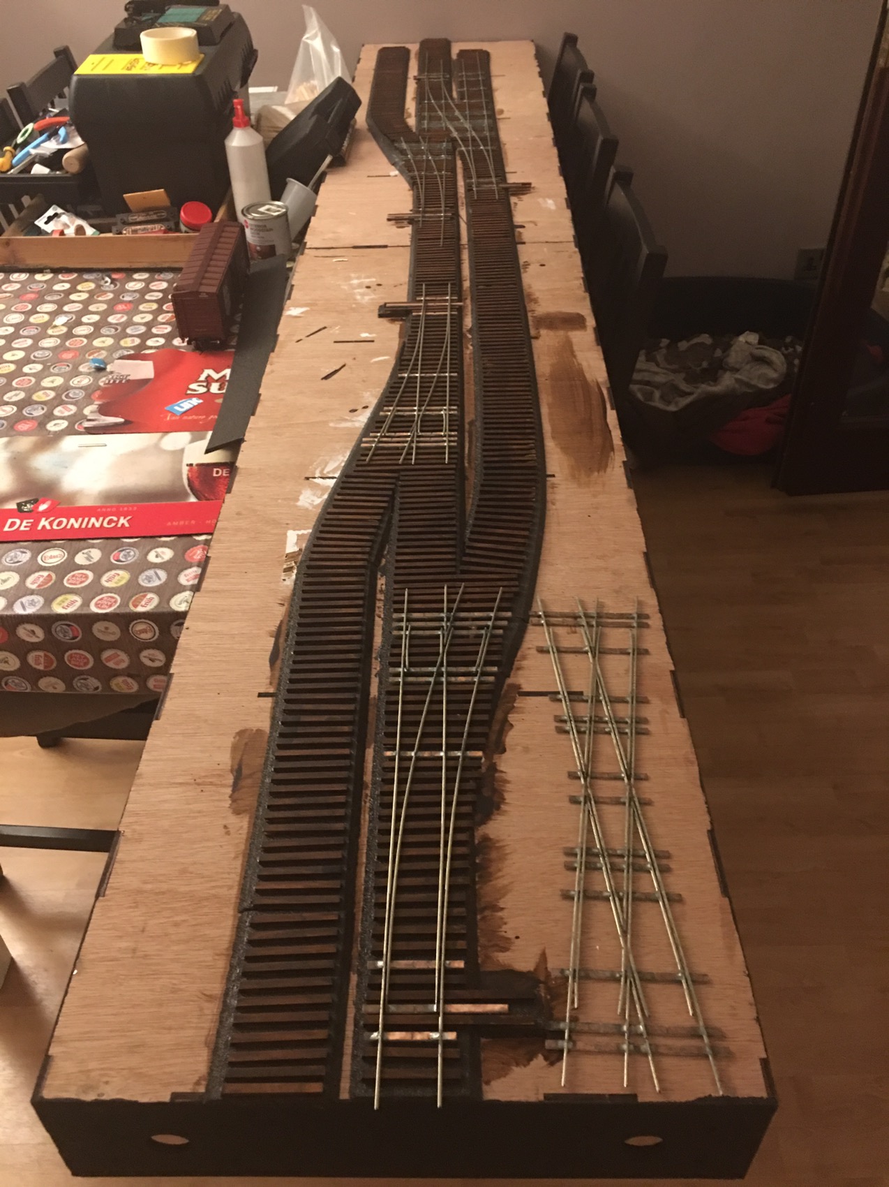
Heres a few shots of me test fitting the track work.
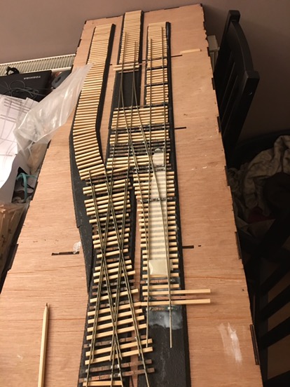
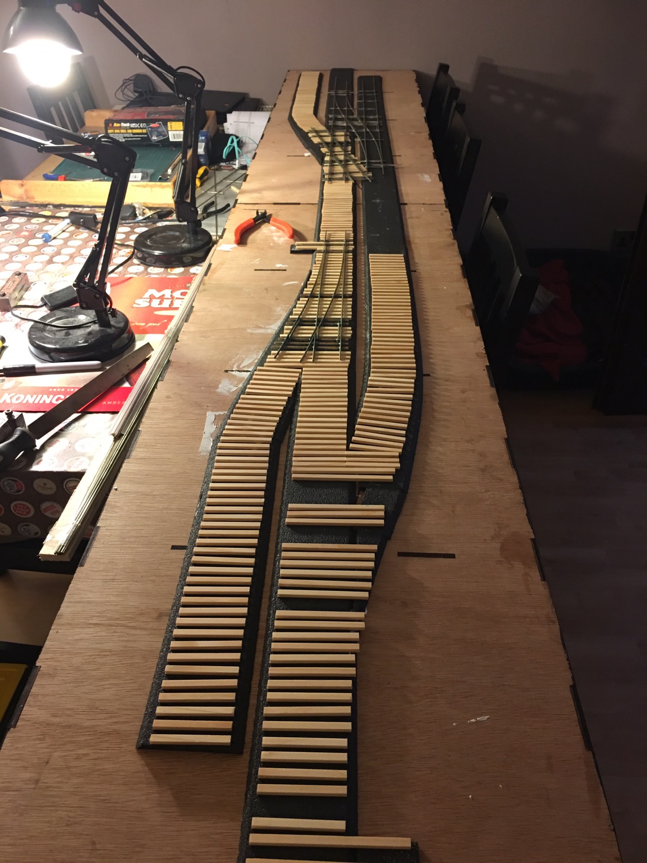
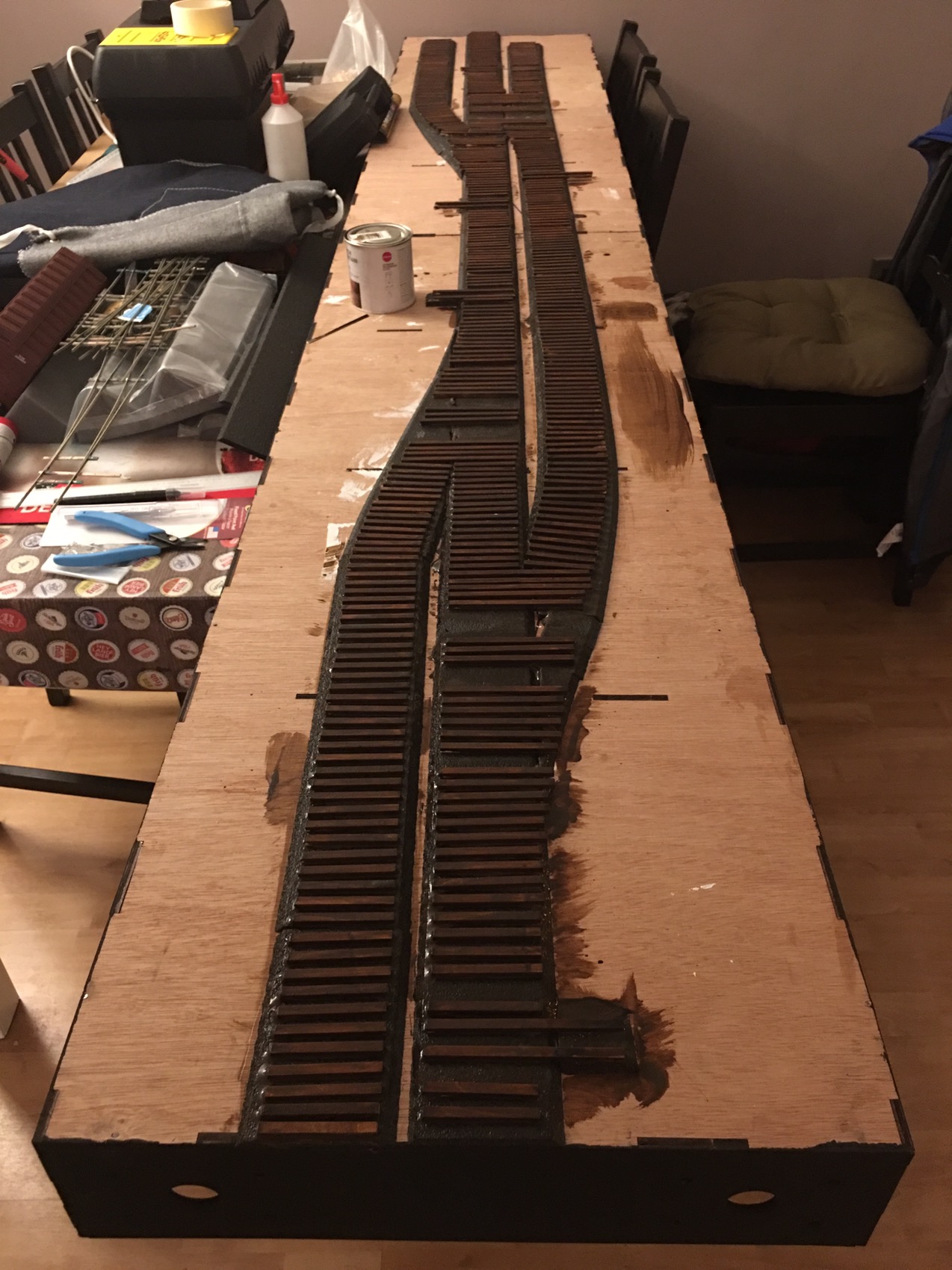
The first two boards contains #5 turnouts (3 of them but only one counts) and a #5 crossover. Having previously fitted the ties i stained them with a dark wood stain.
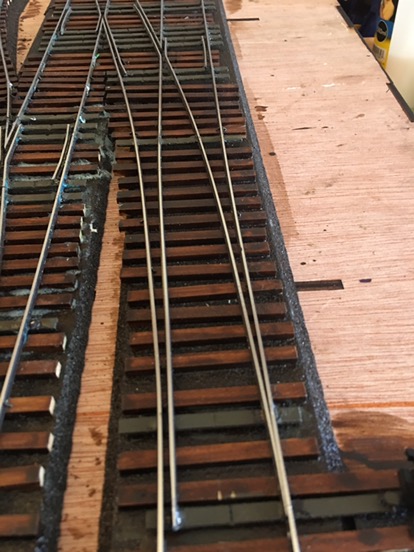
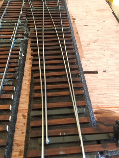
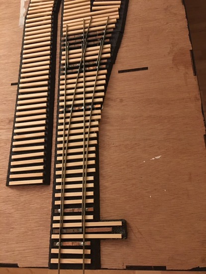
I then test fitted my turnouts
Once i knew everything was lined up i sprayed the turnouts with camo brown car spray paint and cleaned the rail heads with a wood block before the paint dried.
The the hard part started i had the get the rails spiked down, i use micro engineering code 100 weathered rail and medium spikes. Straight away i ran into problems with the road bed offering zero resistance when i tried to drive my spikes. At this point though i was just glad i hadn’t ballasted the roadbed yet.
Having condluded that woodland scenics road bed was no good for hand spiked track i decided to drill pilot holes for my spikes to try and easy the pressure on the road bed. I used a #70 drill bit and a pin vice to make the holes and spiked every 6-8 ties. I will go back and add spikes on every tie later.

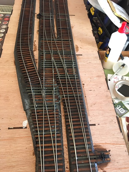
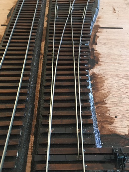
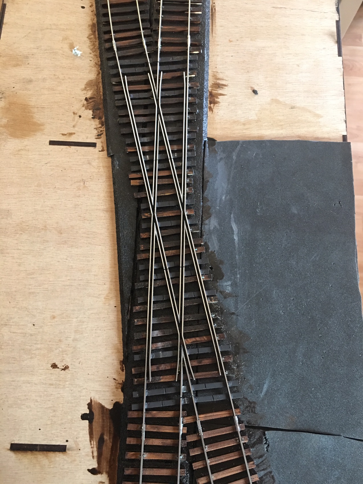
This is a photo after the rails were laid but not yet wired up. Before i installed the track work i had soldered feed wires to the underside of the rails and fitted the wires straight through the road bed and baseboard top before spiking.
My top tips for track laying in this way are:
Start from a datum end and always work away from that point.
Use an NMRA gauge when spiking, make sure you check the rails are in gauge, fit one rail in then use the gauge to fit the second
Use weights to hold the rails in place when you spike them.
To wire up the turnouts i used Gaugemaster DCC80 Auto frogs these are basically the same as a Tam Valley Frog Juicer but much cheaper and without the screw terminals you have to solder your feed wires. The image below shows how i gap my turnouts enabling metal fishplates to be used throughout and a single wire to feed the frog.
I used ground throws above the baseboard to throw the turnouts i decided this was the simplest way for the judges to test the model.
So that meant the wiring was much more simplified. I installed a DCC Bus and connected the auto frogs to it and then to the frog feeder wire.
Test run
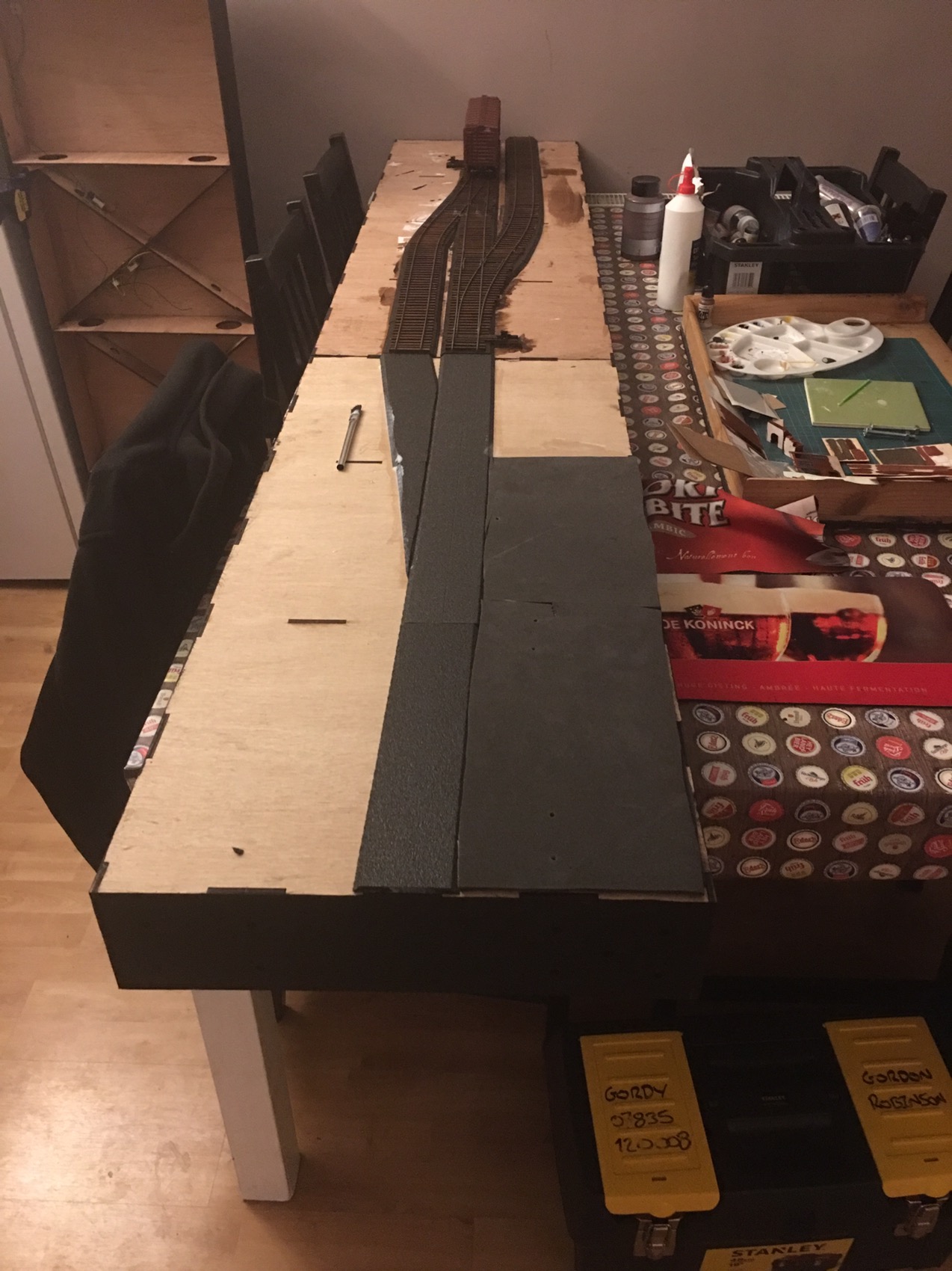
With these boards done i could erect board 3 which will have the crossing on it and i have installed the roadbed.
Board 3
Finished turnouts