While waiting for materials some flex track did arrive, so i took the opportunity to layout Ackerville before making any more progress.


While waiting for materials some flex track did arrive, so i took the opportunity to layout Ackerville before making any more progress.
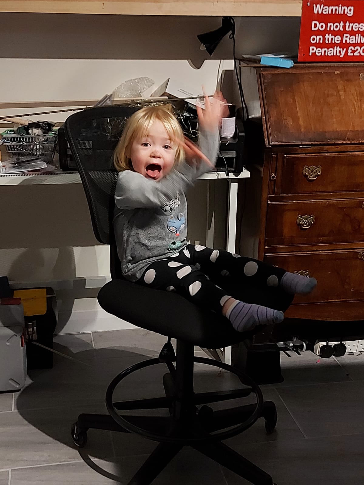
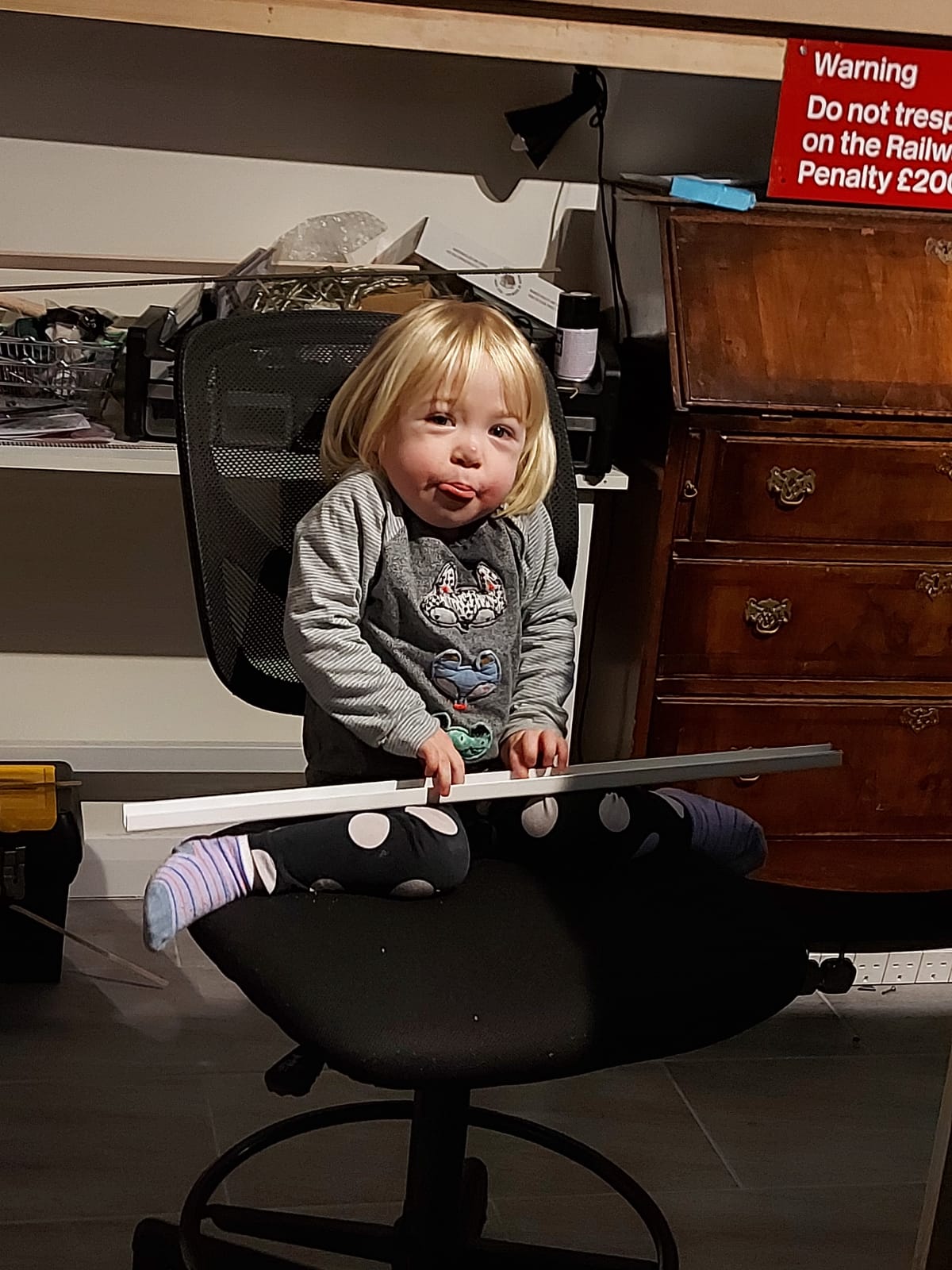
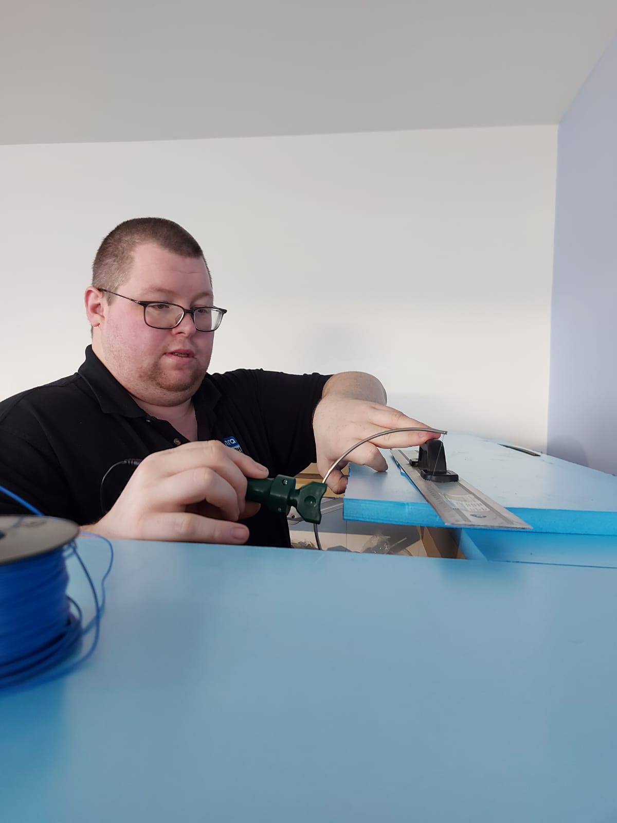
Well our long awaited deliveries have arrived at last! I want to get the ackerville scene finished first so the next few posts are likely to focus on that unless I am awaiting more materials. As you can see I had some help at least with holding things.
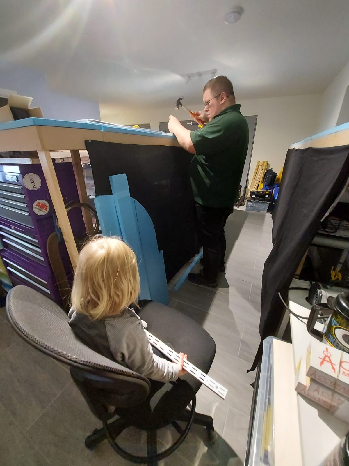

Tonight i decided to add 9 supports for the backscene behind what will be the ackerville module. I even had my little helper Annabel watching me. Now I know you don’t want to be bored with a repeated post about fitting these things so here is your favourite thing a little timelapse.
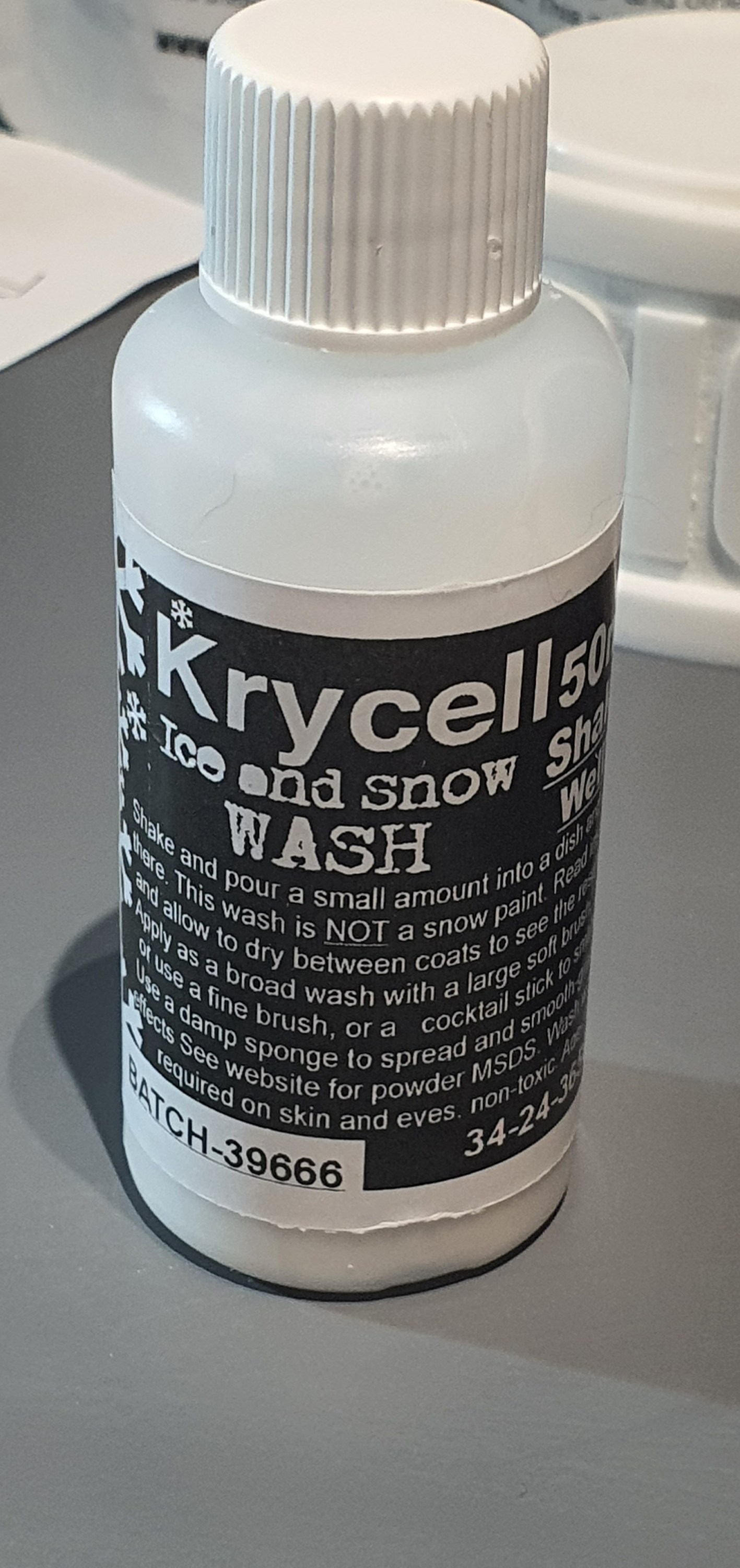
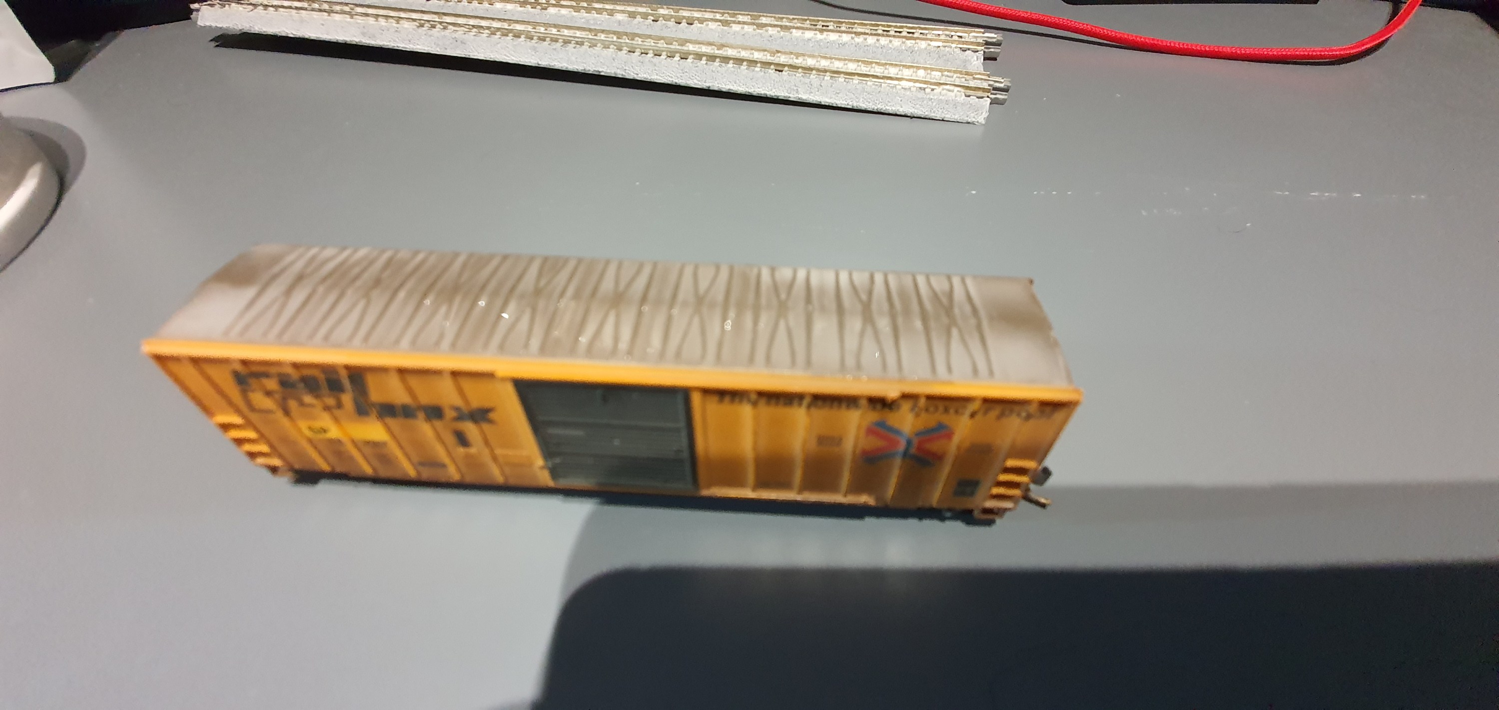
So in my pack of snow products was one called snow wash. This seemed pretty cool and a good place to start with snowy scenes i mean it snows on cars right. Ok down to it this is the wee bottle we are talking about. Now you can skip my chatter and go straight to the experts using it here https://www.youtube.com/watch?v=lk-BERp1RvA
So how did i use this stuff, well to be honest i gave it a good shake and then applied it to any surface that is flat where snow would fall on the car. So roof, end ribs, door guides and rain strip.
When first applied the wash looks like a white paint wash but the snow particles in the wash start to flow to the edges and into the recesses of the model as it dries. This was the first coat but I applied a second and then used a dry brush to move the settling material to the edges of the roof.
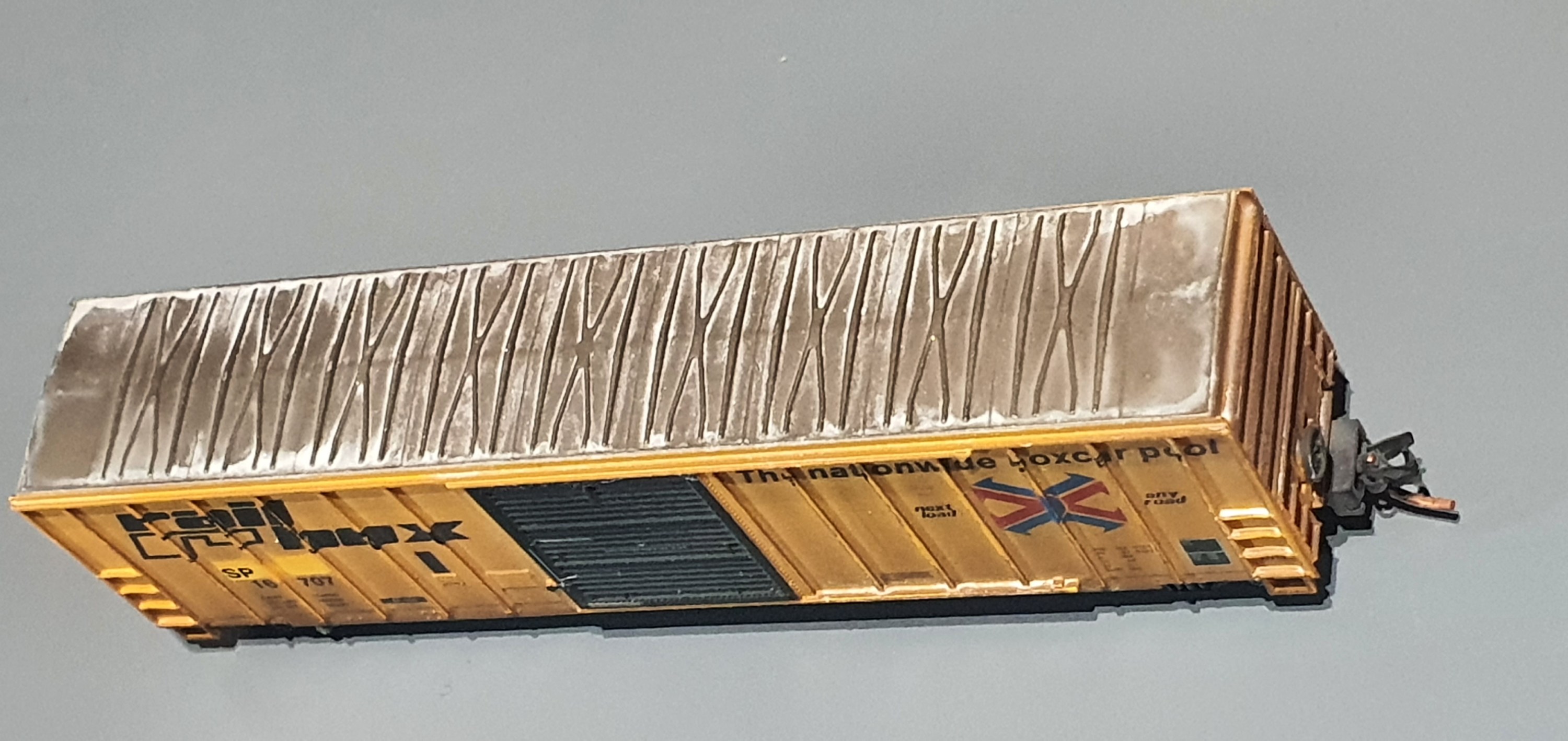
I then detailed the ends and even managed to get the effect of melted and re-frozen snow on an end rib.
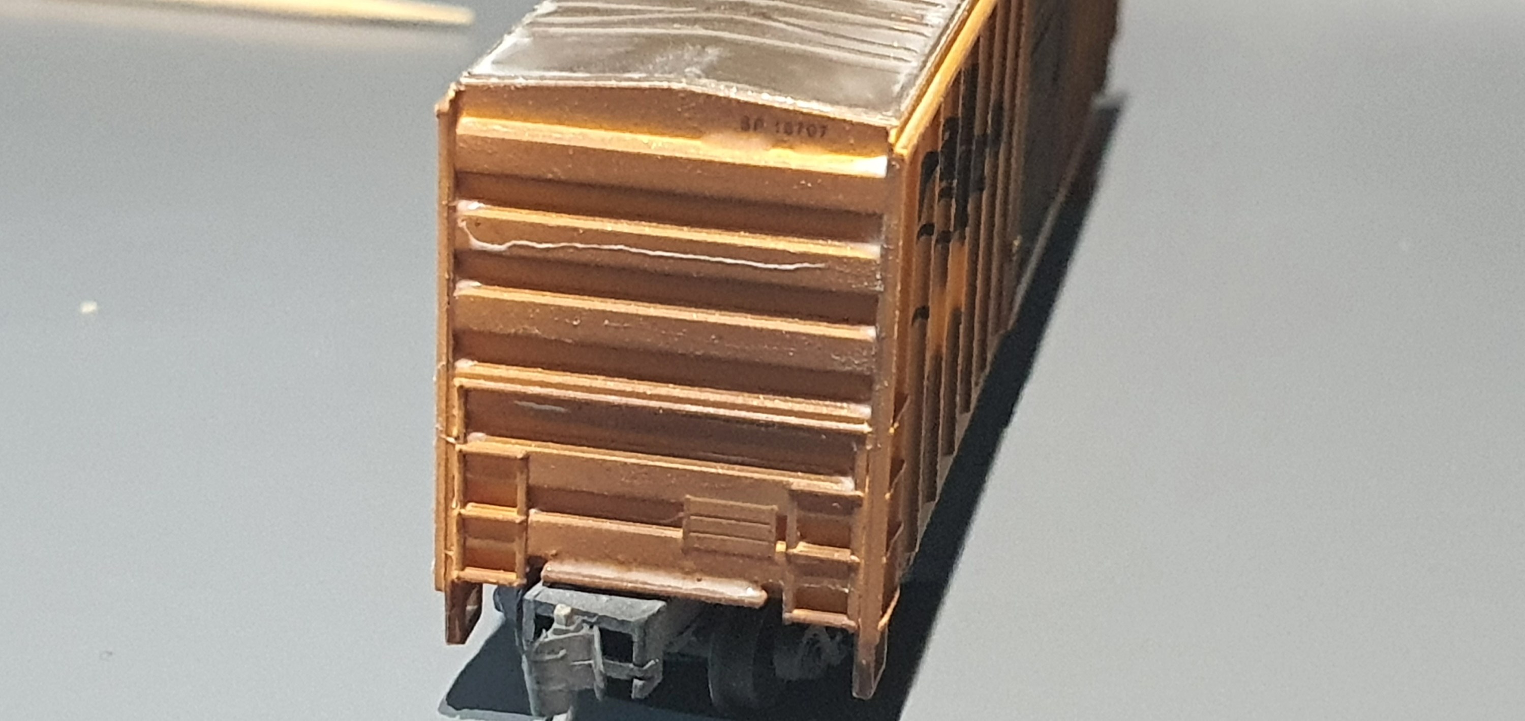
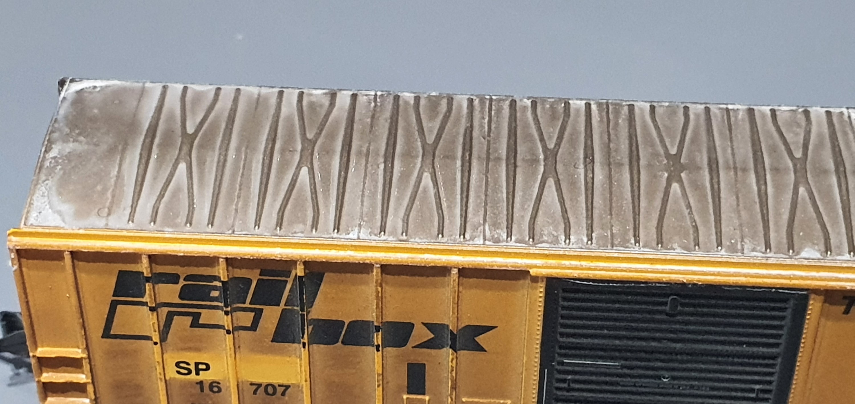
So as you can see its a nice build up of frozen snow in the recesses fo the car to give that frozen effect. Fresh snow would blow off the car when moved but the frozen ice below the top snow layer is left in extreme temperatures and this is what I was going for.
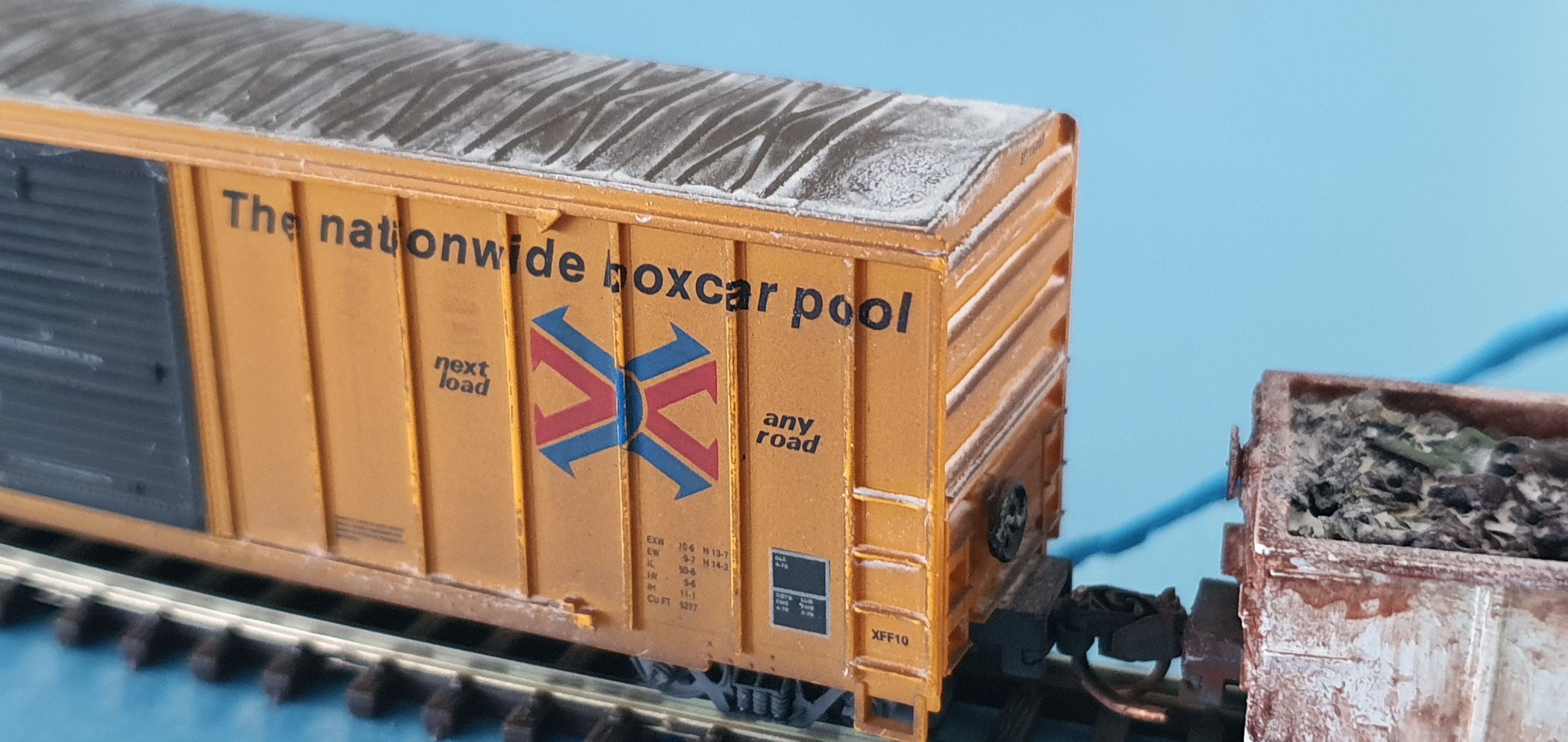
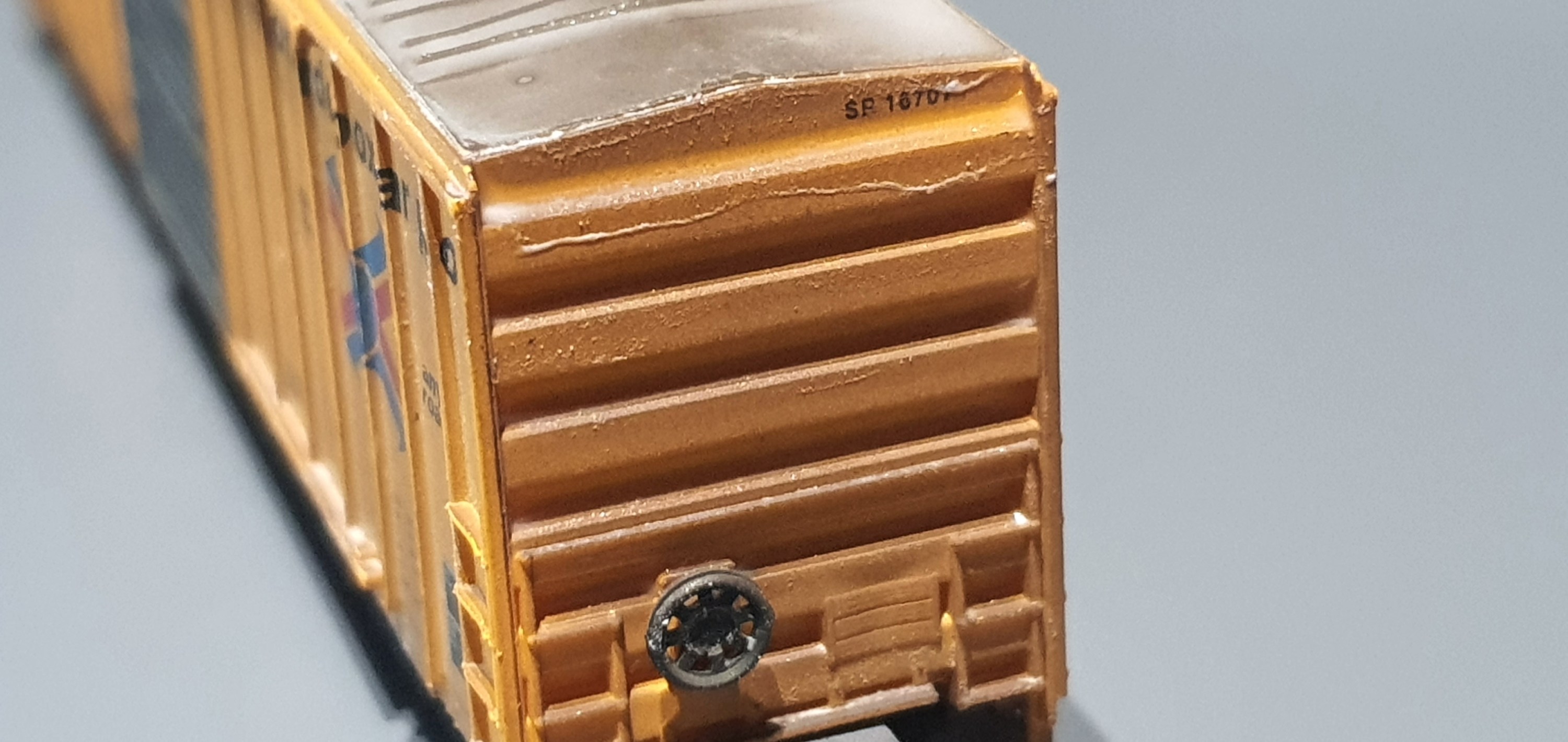
Here you can see the snow collecting on the end grab irons/ladders and build up in the door runner.
I really reccomend this product if you are going for a winter scene. I did some more cars whilst I was working at the weekend so I’ll add more pictures of some other stuff in a post later in the week.
Oh looks like the postie is here so best be off, hopefully he has some materials for this weekens projects.
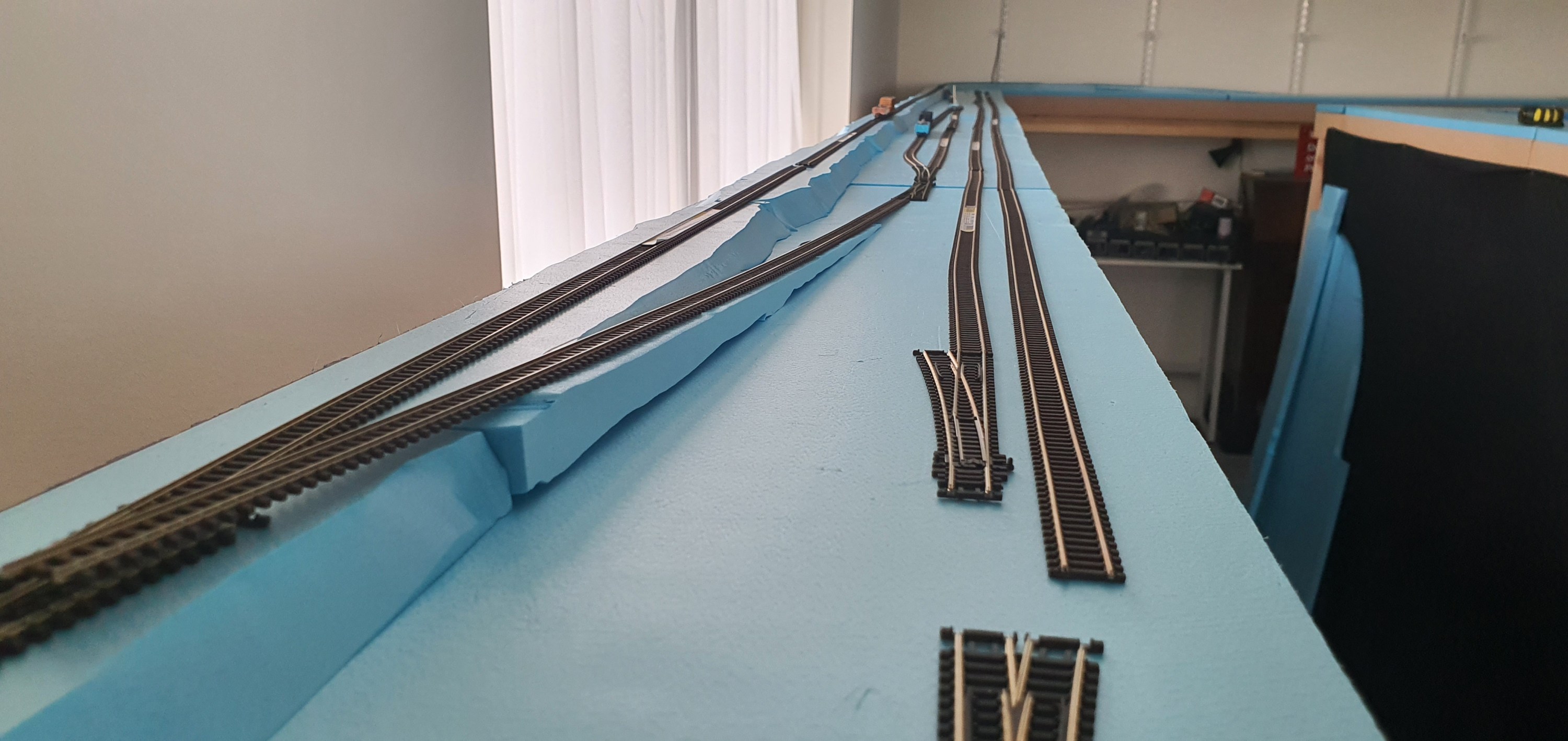
Yesterday you saw how i got the foam blocks in place that would support the WSOR mainline. Big square blocks don’t really conform to nature so I will need to add the embankment slope.
To do that I used a hot wire foam cutter to take about a 45 degree angle from the base to the top of the sides of each foam block.

I didn’t try to be too even as one its really hard to do free hand along a 4ft length of foam and his whole area will get covered in sculptamold before any scenery goes down here.
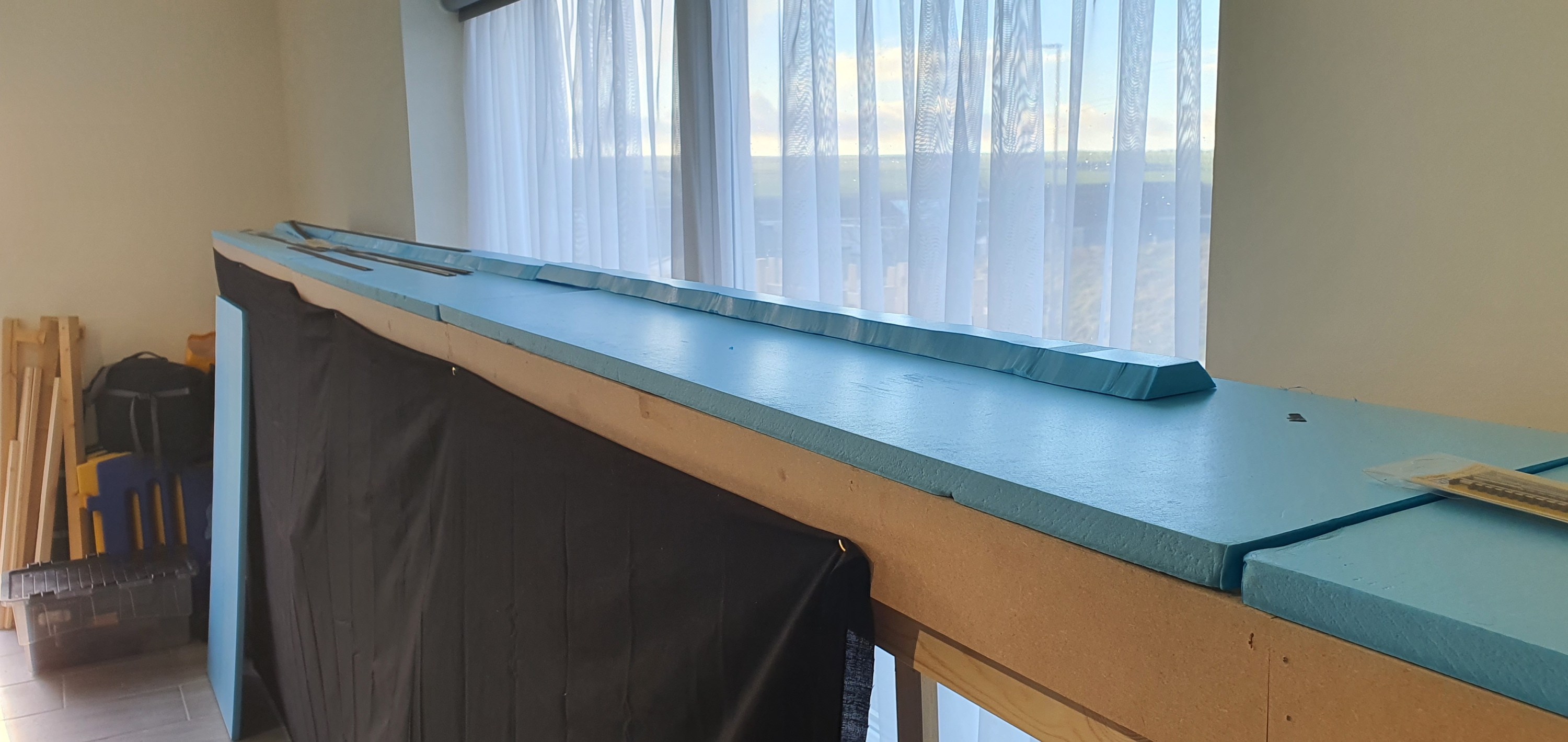
Carrying on from the first image in this one you can see that the profile has been cut into both sides of the foam block to form the embankment.

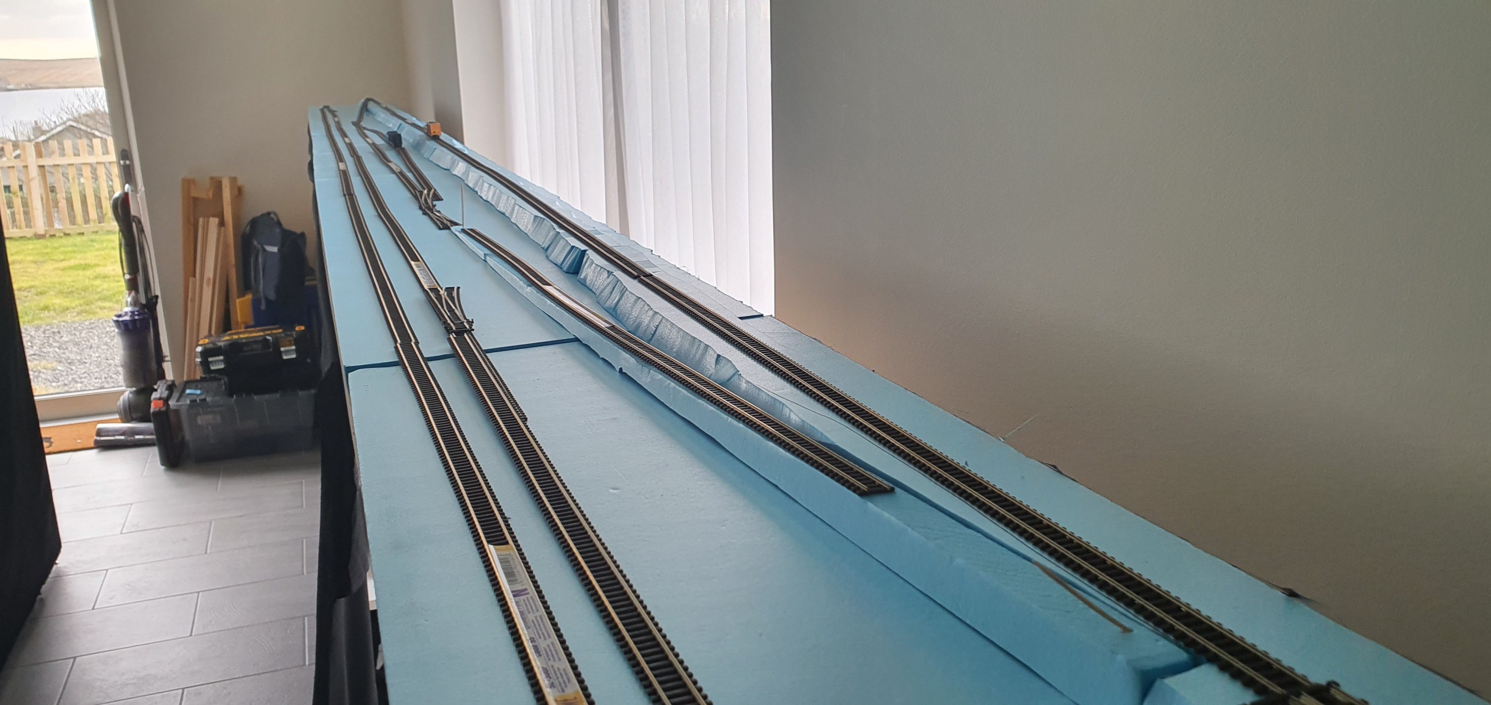
At the southern end of the yard I added a 2% grade, this is just for variety really but there are full trains that will need to negotiate this incline to access the WSOR Milwaukee sub during op sessions so I wanted the slope to be more gentle as this will be more than just dropping a few cars into or out of the yard as at the Northern End. In real life because of the grade crossing just north of the yard most switching and interchange is done at this southern end.
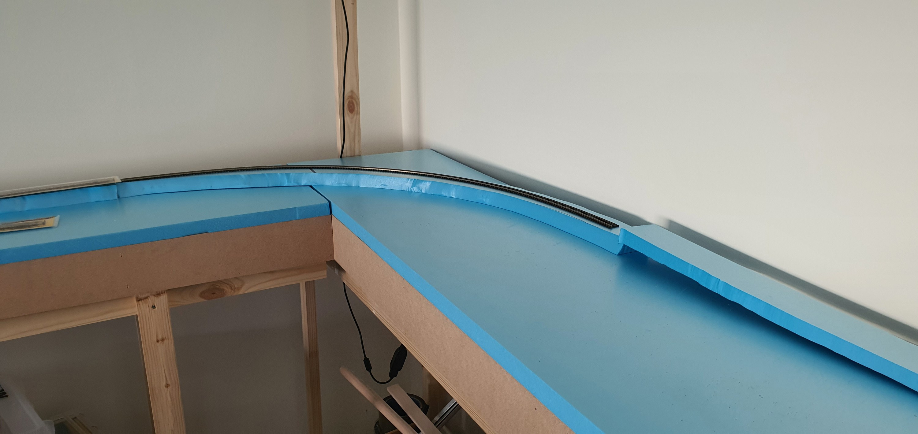
The raised WSOR mainline continues around the corner onto the next section of modules before the grade brings it down to level again with the CN before Rugby Junction. The highway overpass will cross the module about level with the leg seen to the left of the picture.
So now we await the arrival of a few bags of sculptamold and we will get this scene progressed.

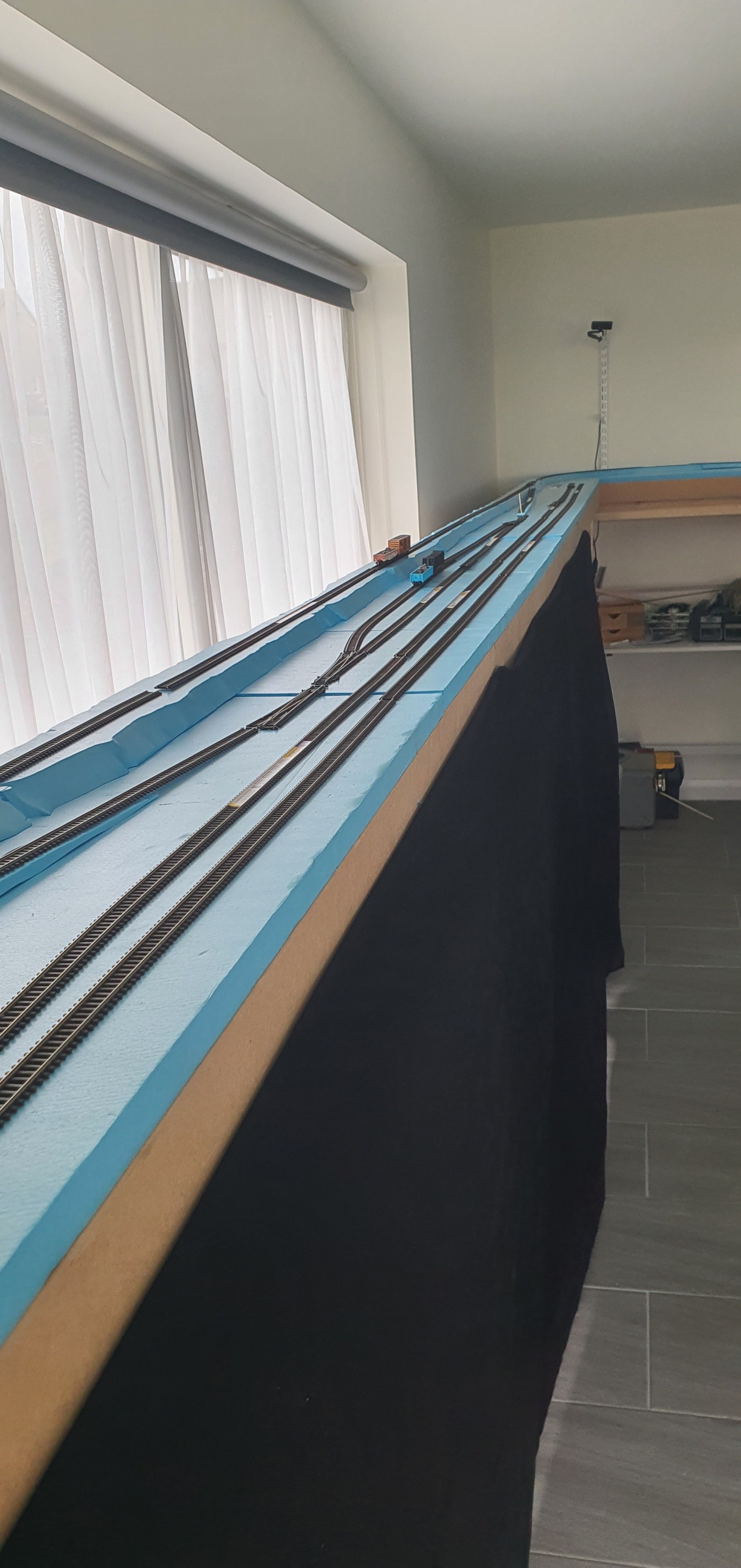
Here finally is a complete overview of Ackerville with its base foam just placed onto the module tops. This will be a signature scene on the layout I am lucky to have such a long aisle in which to place it. Crews here will have plenty of room to complete their work.
Well its Friday so grab yoursleves a wobby pop or soft beverage of your choice and head back to your workbenches.
In a follow on from tuesdays post, which you can read here its time to put some scenery base in for the Ackerville scene. This is the rough building blocks that will be used to for lanscape features to support track, roads and structures.
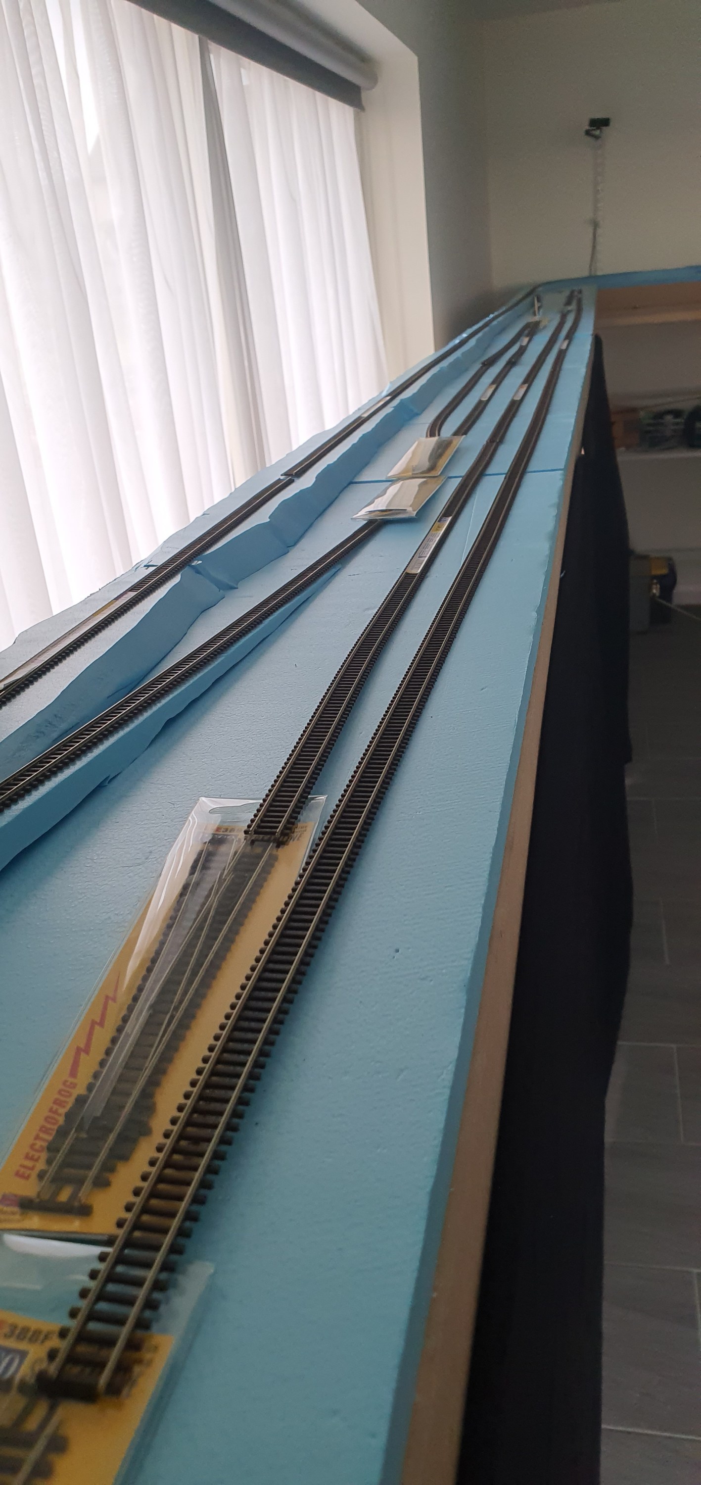
I started by slicing 70-80mm strips of 20mm foam to use for the WSOR mainline which is elevated above the rest of the yard.

These square blocks were then place roughly in position with the turnouts at the yards Northern end.

To get from the WSOR mainline into the yard I cut section of foam with a grade of 4% to drop the main from 20mm to 0mm height in 500mm. A small inset section was cut into the 20mm thick foam to allow the two sections of foam to come together.

Here is a side view showing the incline and height of the WSOR above the yard and CN main. It looks quite high but based on the images I found the line is about one fright cars height above so this is actually a little lower than reality but 20mm feels right and we are already compressing the scene so perspective is important.
The foam does’t go all the way to the backscene so that there can be fall away before the tree line as it is in real life. I kept adding foam blocks until I reached the Southern end of the yard.
The next job will be cutting the slope of the embankment into both sides of the foam blocks join us tomorrow to see how that comes out.
Ackerville has to be one of my favourite places on the Waukesha Sub Division so it had to be included in my layout. Its a small interchange yard between the Wisconsin & Southern Railroad (WSOR) Milwaukee Sub Division and the Canadian National (CN) Waukesha Sub Division.

The area in red what will actually be included on the layout. Plans like this are great for trackplanning but pretty rubbish for planning the composition of the scene so we need a photo or ideally a series and the internet is a great source.

This overall view, taken from Slinger road looking south, shows that we have a nice scene boxed in from the front and rear by a tree line. Other than some lineside equipment boxes the only other structures are a communications mast and a highway overpass. As we look at this photo the left hand track is the WSOR Milwaukee Sub Division and the CN is on the right. The left hand tree line will be our backscene and the right hand tree line will be removed as it will be the edge of the layout and we want to be able to see our trains.
Whilst an overhead shot is really nice to have, what we need to see ground level elevation is a shot taken from ground level. So back to the internet to see what we can find.

This photo of WSOR local L249 working the yard shows that whilst most of the forground is flat the WSOR mainline to the rear is actually elevated with two sharp grades used to access the yard. You can see how the tree line dominates from behind the WSOR embankment and will make a fantastic background.
Now this images is in summer and because I am totally colour blind I have decided to set my Layout in January. Therefore we need snow lots of snow so lets try and find a picture of Ackerville in Winter.

Its a WSOR take over, well not quite here you see CN local L510 working the yard with an exEJ&E locomotive still in original paint tied down in the yard. As that local which runs from Fond-du-lac to Waukesha as a turn, i.e. it comes back, is paused the T004 Horicon to Janesville WSOR transfer exercises its trackage rights between Slinger & Grand Ave Waukesha. Hopefully we’ll soon be recreating this ourselves soon in on our own minature version of this busy section of mainline.
Things to note for the scenery are the switch stands in the yard and the tyre tracks from MOW trucks at the side of the CN mainline. Its little details like those that make all the difference.
Join us on Thursday as I start to cut some foam and make a start on laying out the scenery base for Ackerville.
We previously looked at modifying the Elfa twin slot uprights to add an additional screw hole so that we can use them to support the upper deck, back scenes and eventually the lighting for the layout. The uprights will be fitted at 600mm intervals meaning i need 33 in total. However I was only able to get 11 of these from my supplier, I am hoping to get the remaining 22 shipped to Orkney by the end of this week.

With only a limited number of uprights it made sense to work on the hardest to reach areas first. this means working in the area marked in red on the plan below. As the layout is modular i was able to remove the left hand 4 modules of the layout and the intermediate module on the right hand side before moving the whole section againse the wall out to enable access to the rear. If you were not concerned about damage to the wall of course you could just ignore my step and screw the uprights straight to your wall.

So lets get on with getting these things fitted.

I levelled up the base of the upright with the base of the module and marked the hole for the upper screw. being sure to ensure that the screw would be going into the cross support of the module and not hitting any of the brad nails used during the modules construction.
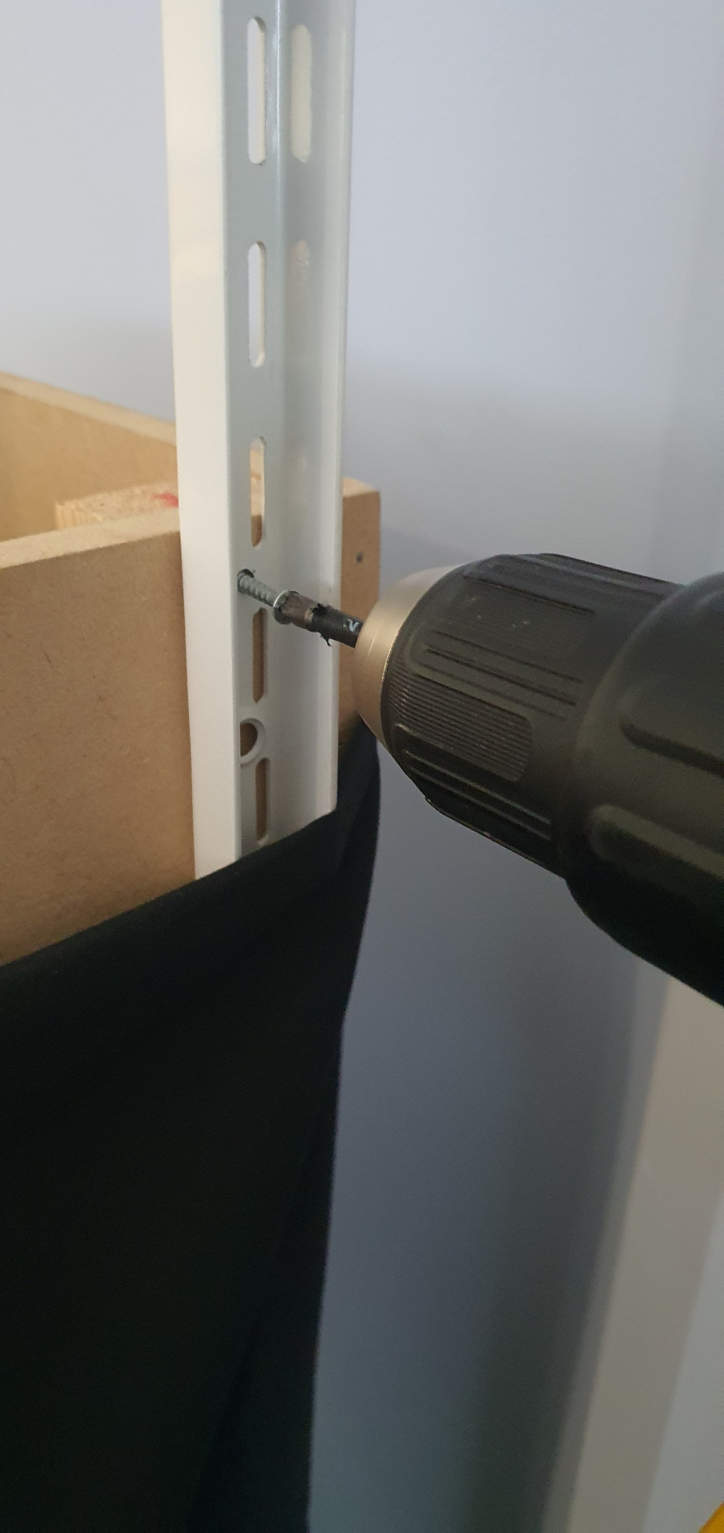
Then I used 3.5mm x 30mm screws to secure the upright.

Using the top of the module I squared the upright to be vertical and then ran in a 5x60mm decking screw (mainly because i had them on hand) into the lower hole securing everything square. These are probably over kill but this should prevent the uprights from moving when under load.

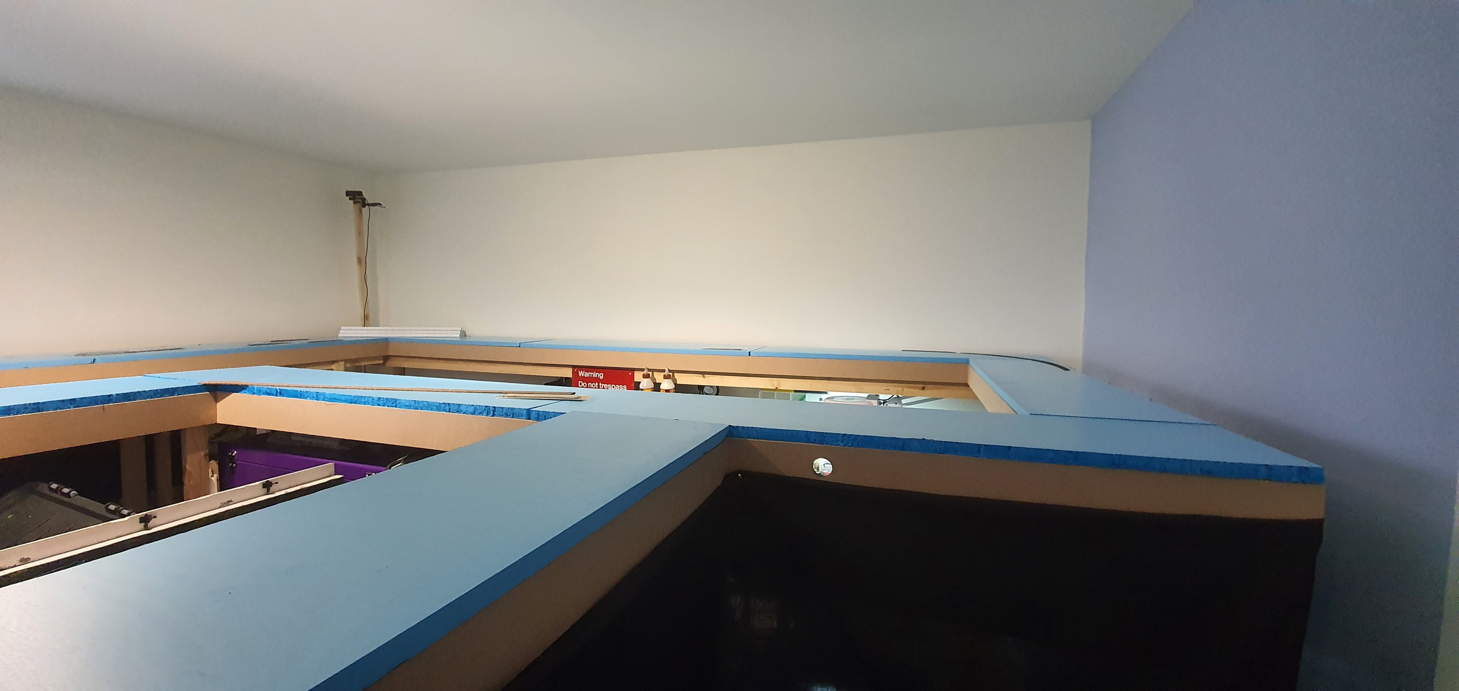
Here you can see what the uprights look like in place on the module I removed to allow the large rear section to swing away from the wall. it certainly was alot easier to do this module than the others.
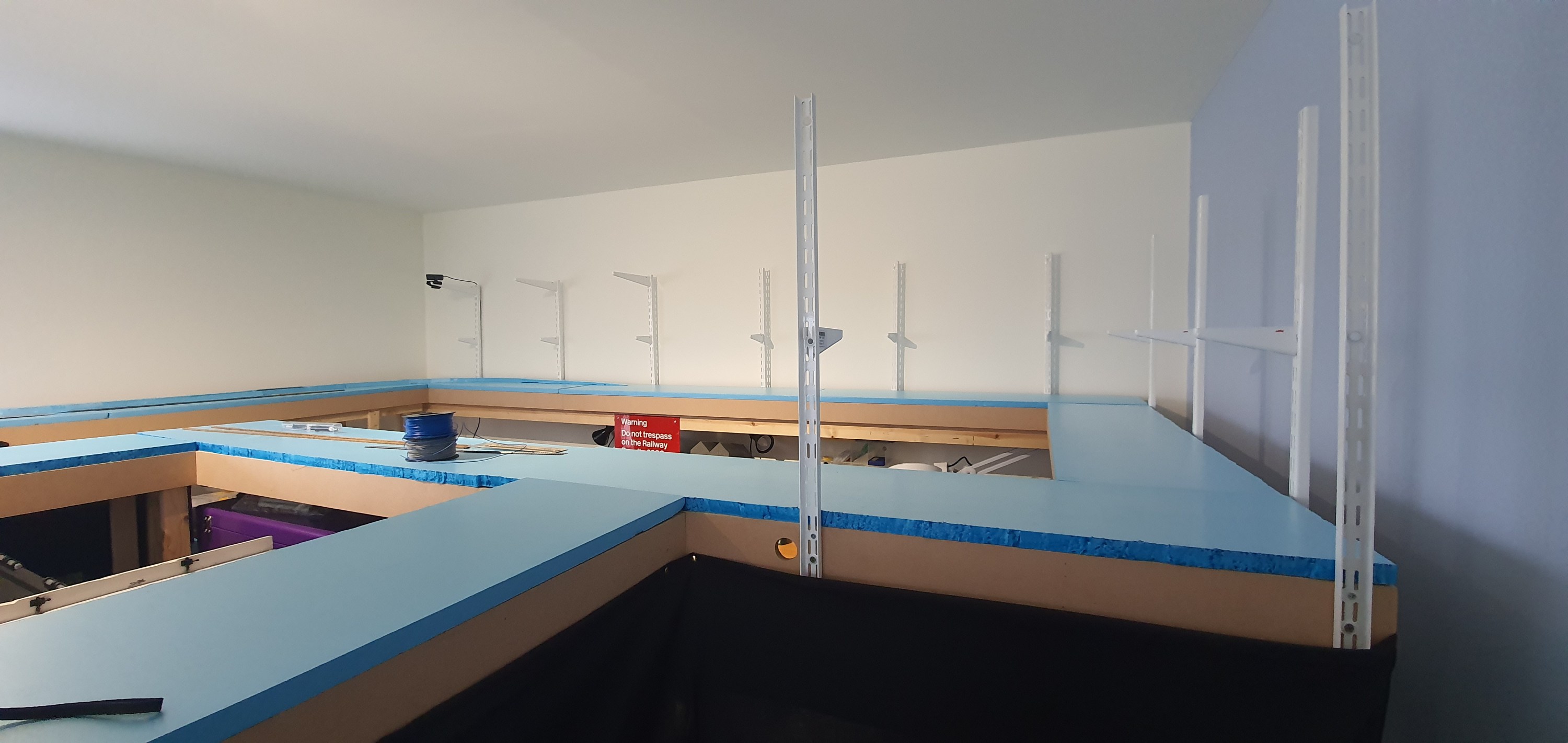
Here you can see the completed view of all 11 uprights in position. There are above my workshop area and over the coming weeks I’ll be adding the back sceneswhich will permantently take away my ability to take these overall shots.
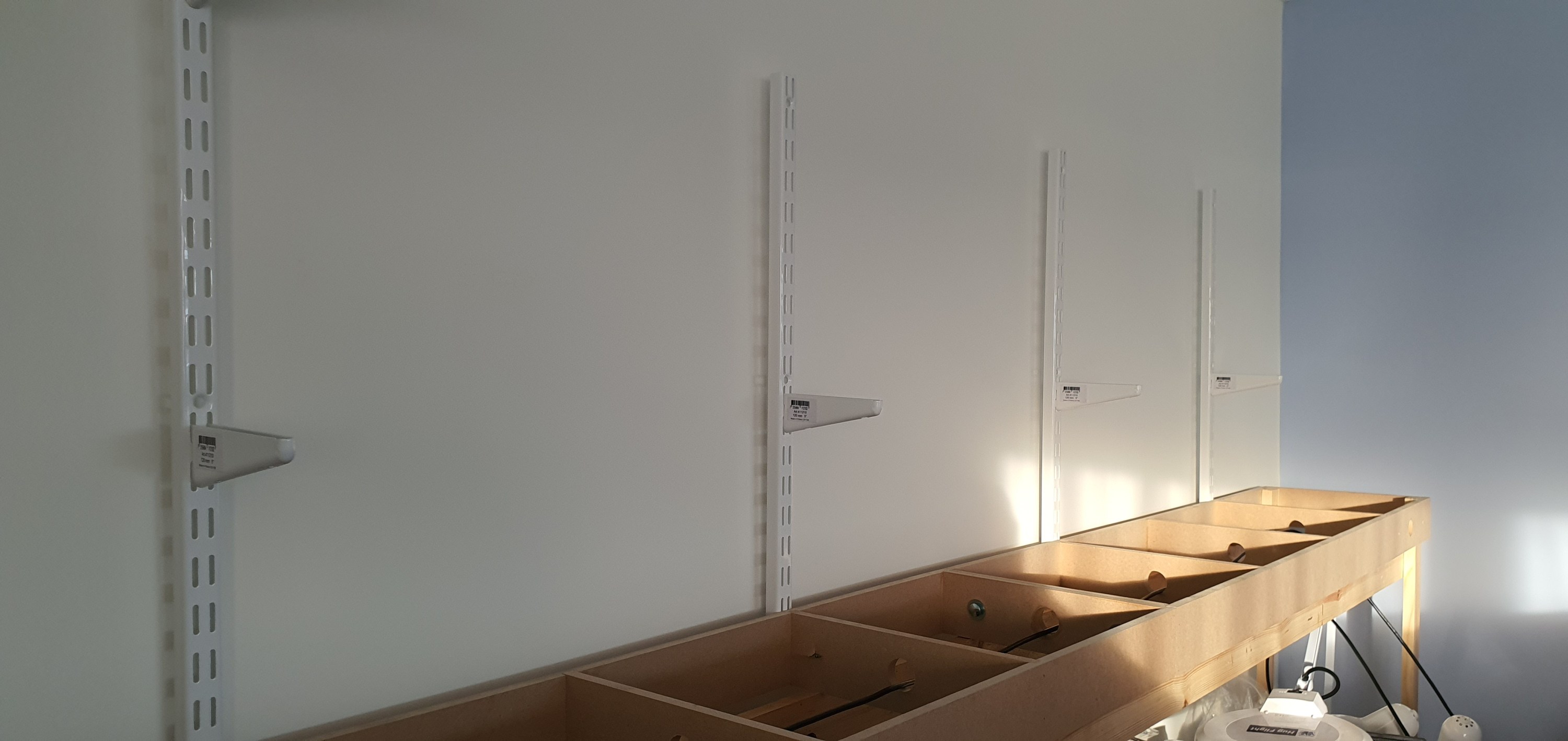

In these two shots taken whilst the modules were detached you can see the brackets for the second deck and eventually the lighting rig. The second deck supports are 120mm long which will enable a small shadow box effect above the lower deck. The upper supports are 320mm and will extend just in front of the lower module deck supporting lighting for both decks and completing the shadow box look.
Look out for tomorrows post where we will look at scenery planning on the Ackerville section of deck one.
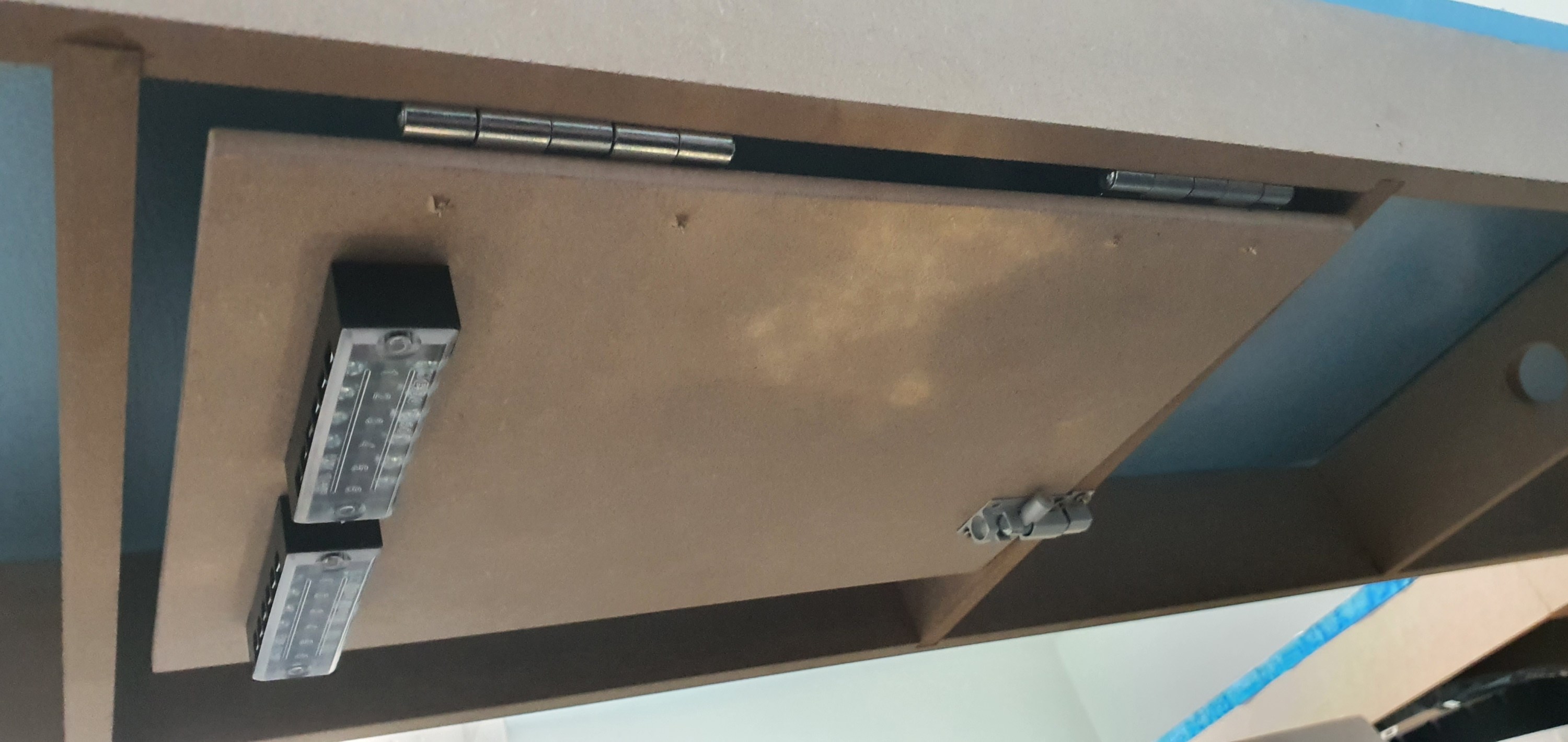
I really don’t want to have to trouble shoot electrical gremlins under my layout, who does. So I’ve designed electrical boards to mount, DCC boosters, block detection units, circuit breakers etc.
To make the boards i used A4 6mm MDF sheets from Amazon. Onto these are mounted 63mm butt hinges and 38mm barrel bolts. I threw away the supplied screws and replaced them with 3.5mmX12mm screws. All the ironmongery came from my favourite store iornmongry direct were a pack of 200 of those screws was less than £2.

To one side of the board is fitted a screw terminal block. This is really useful when wiring and prevents cutting feeders or straining wires the wire from the track comes in on one side of the wood and then the wires go from the terminal strip to the DCC components on each board keeping everything neat and tidy.
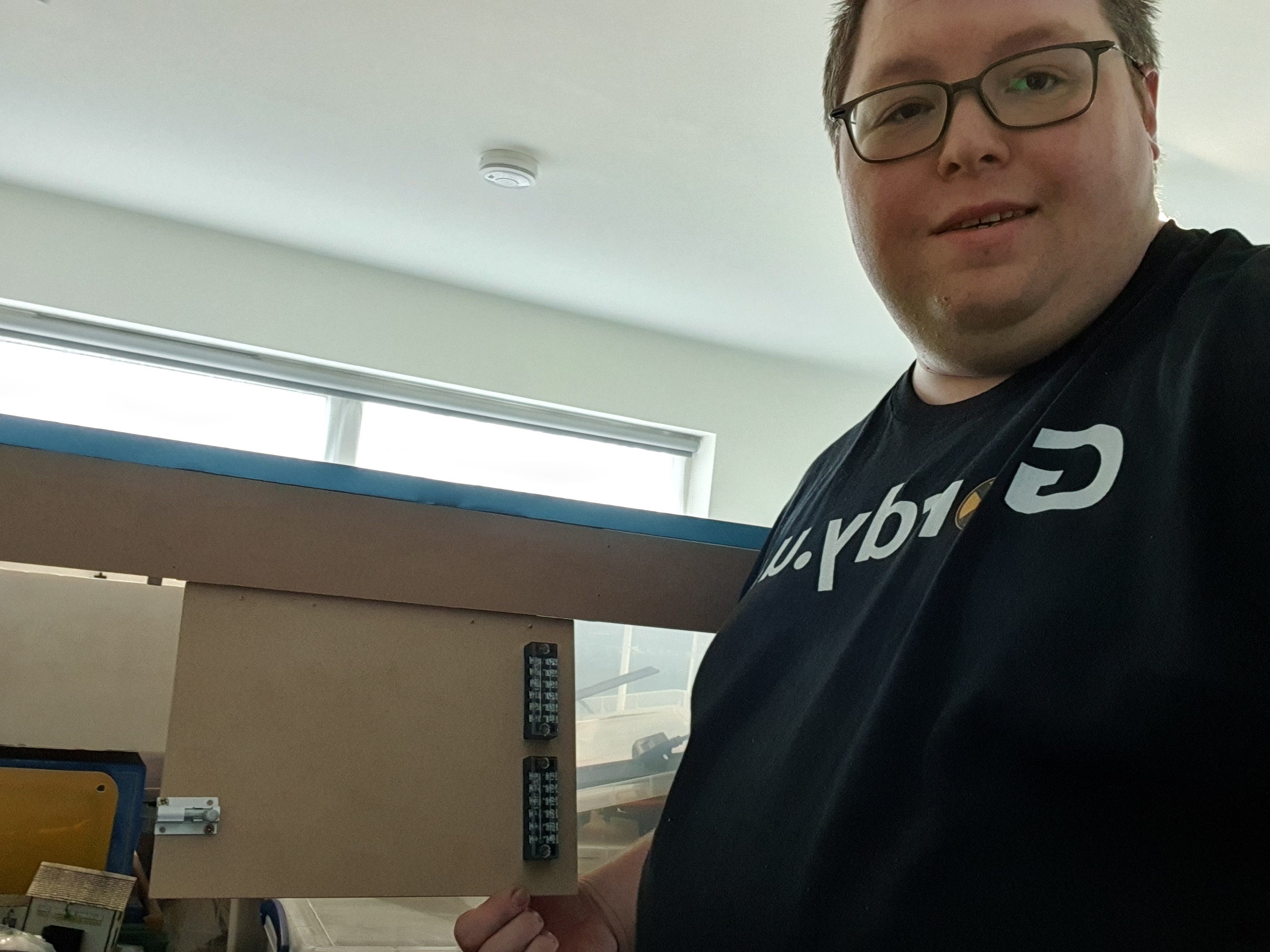
When the bolt is released the board swings down to the front of the layout at a comfortable height to work at either sitting or standing.
Well thats the prototype done. Now 9 more to get built.
Those who use Anyrail software to design their layouts will know about a little feature called Print, which will allow you to print the trackplan in 1:1 scale. However, if like me you have a track plan covering your whole room hitting print will print the whole room including the dead space in the aisle. Thats a lot of waste so we want to try and reduce that as much as possible.
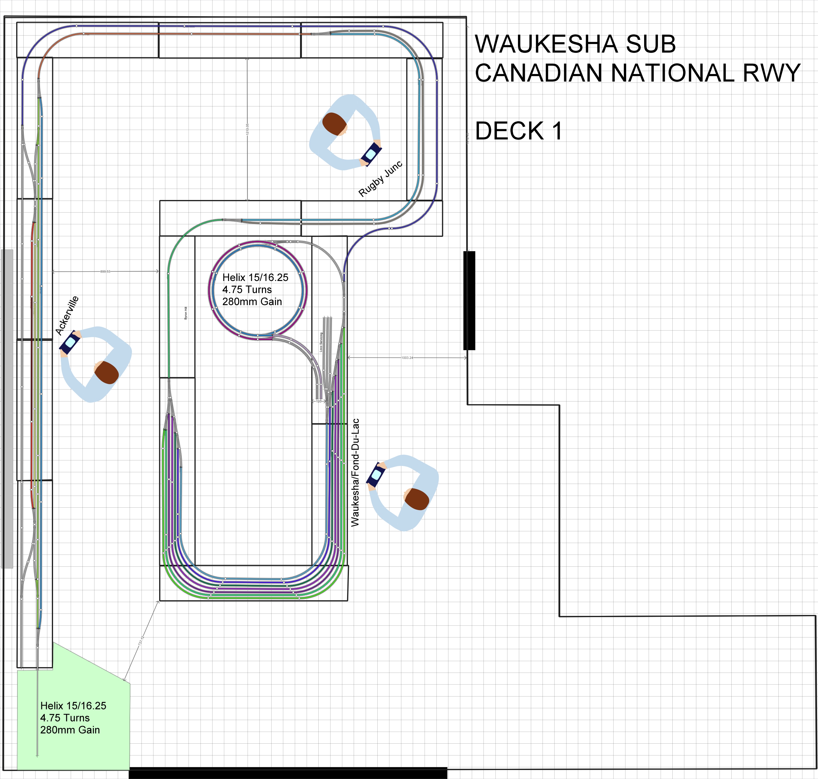
To do that we are going to take each section of the layout and copy it into its own anyrail project that won’t waste paper when we print it off.
The first section we’ll do is Ackerville, thats the section on the left hand side of the track plan where the WSOR interchanges with the CN.
Step 1
Open a new Anyrail Project and change the work area settings to be the size of the Ackerville boards
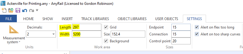
Step 2
Also make sure that both projects measurements systems are in the same unit of measure in this case Metric decimal units (mm)
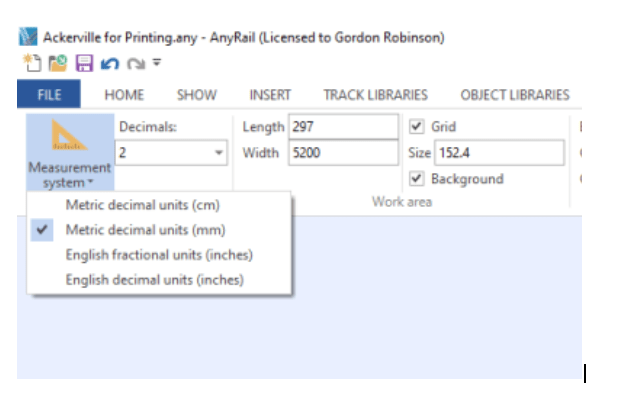
Step 3
Highlight the area on the original plan that you want to copy across. Once highlighted use CTRL+C to copy the area.
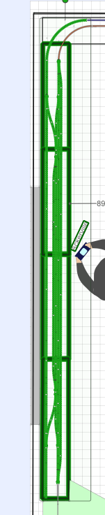
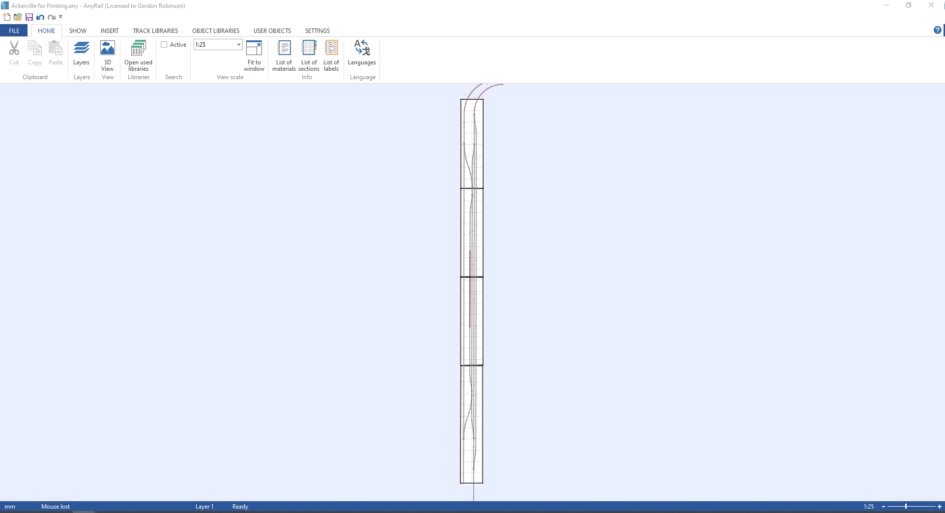
Step 4
Go over to your new project and use CTRL+P to paste the items. Line it up with your work area and then you should have something that looks like this.
Step 5
ok we are ready to print. Go to File>Print
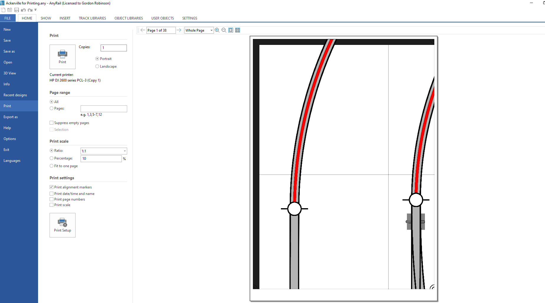
Step 6
All we need to check now is the print settings.By default Anyrail is set to print off at a scale of 1:10 so you’ll need to change that to 1:1. Next uncheck the ‘Print date/time and name’ and ‘Print page numbers’ . The final thing to do is go to Print Setup and make sure that you have the size of paper in your printer selected.
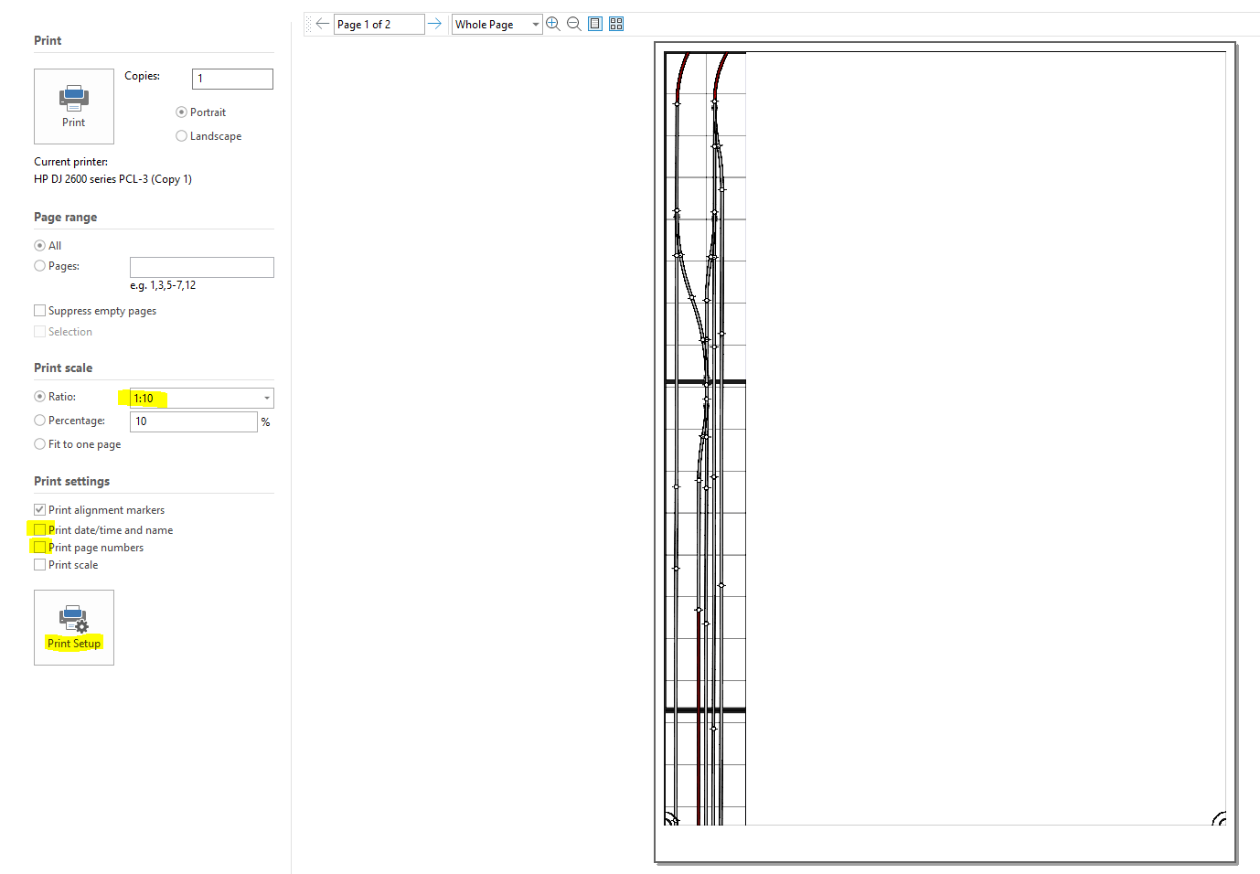
Well thats it you can hit print and in my case we’ll get 38 pages that we can use to accurately mark out where the track will go and start planning scenery on this section of the layout. Printing the whole plan would have been 782 pages.
Well till next time folks hopefully we can get some time in the train room tomorrow to dismantle the layout and get those supports fitted.
As I said in my pevious post materials are low on the ground here at the moment, there are plenty of wee jobs to be getting done but there are not enough materials to actually finish anything. Therefore this is a post about drilling a hole so thats your hint to run give up reading the rest of this update.
The Plan
To support my backscenes and upper deck I need to use something, there are also challenges in so much as this is a modular layout it may have to come apart to move to a new room in the future. So we need to bear that in mind. we also don’t want to damage the walls of the room and don’t want anything to thick or heavy making the layout smaller.
Shelf layout folks have for a long time used twin slot shelving to mount their layouts and the same theory can be used to make a double deck modular layout. Of course we need to be mindful or the weight we are adding above deck one. By adding the short section of twin slot u channel we are adding a lever and anyone that has used a prybar to rip open a pallet will know the pros and in this case cons of doing that. Whatever force is applied to the uprights will be trying to rip apart the bottom module, so care is needed.
Backscenes & Upper Decks
The back scenes will be 3mm MDF i am still not sure on if these will be painted or photos but as I am planning on a winter scene for the layout then I think all options are open. Otherwise I would be reccomending photo backscenes all day long. Whats important here though is weight and well there won’t be much acting on the support from the backscene.
The upper deck will only be 120mm wide and cut from 15mm OSB this is heavy but its strong and won’t need any other supports underneath that means we can have that rail height only 250mm above our lower deck and have the backscene 228mm (9inches) high below it. Again not much weight. I may add a lighting deck to form a shadow box at the very top of the upright and so long as nothing is placed on here I think we will be fine. Also using metal uprights means I can use magnetic tape to have an easily removeable backscene without needing to dismantal the layout.
Where to Start
Well as always material is in short supply here in Orkney and I could only get 11 636mm uprights. I have used Elfa uprights for a number of years and these can be purchased in the UK from Iornmongrey Direct. It doesn’t really matter where you get your materials from but its important to stick with the same brand. Not all twin slot is created equal and pretty much no two brands play nicely together. Elfa is great for model railroaders because they do brackets from 120mm up to over 500mm which is really a very wide shelf layout. Also being 2mm thick steal they are strong and support a huge 55kg per bracket.
As we only have 11 of these I am also going to start with those in the most awkward place on the layout to access above the workshop area. This will involve dismantling part of the layout but once done there shouldn’t be a reason to repeat doing this for any future jobs as the magnetic tape will hold the backscene in place.
Out of the box each upright has three holes for screws 290mm apart. Thats grand for on a wall but for me that would mean only one screw per upright and thats a little much I think. So its time to get to drilling a hole. How much you’ve been looking forward to a blog post on drilling a hole, well here it is.


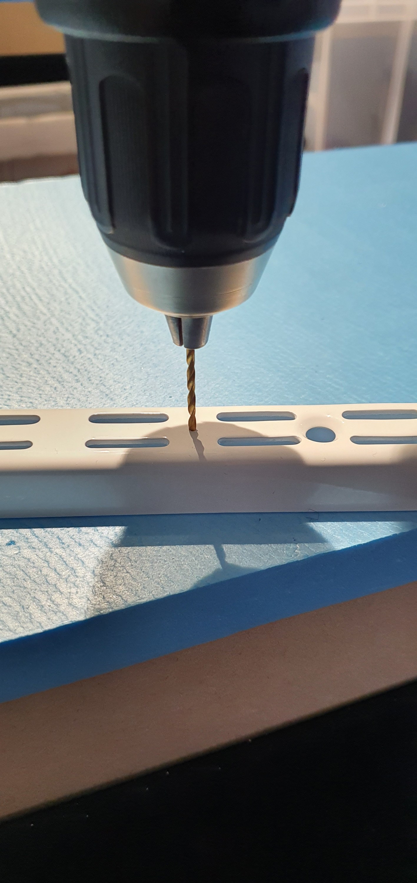
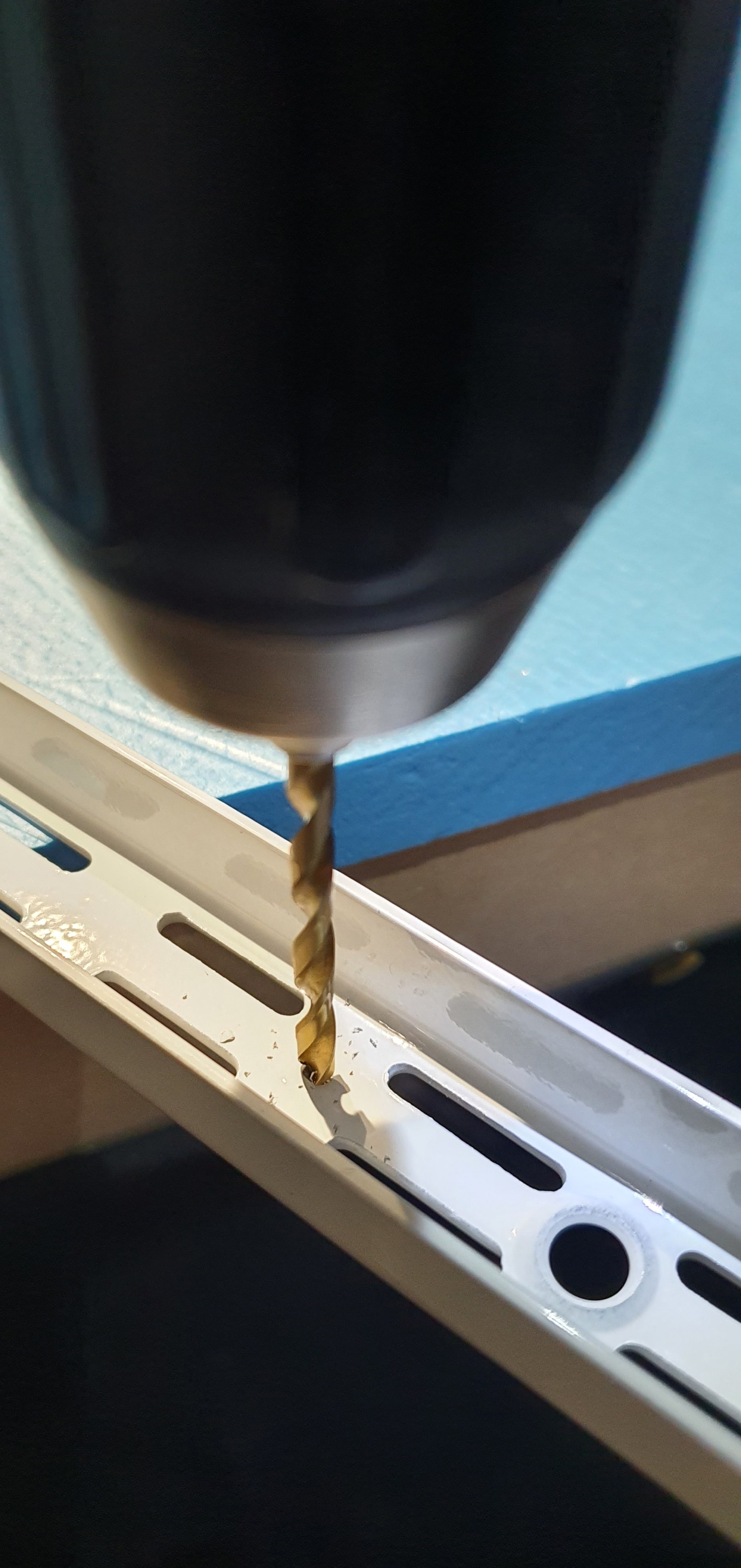


Right we have 11 of these now just enough to do along that back wall above the workbenchs, now I need to find an extra pair of hands to dismantle the layout.
Till tomorrow 🙂
