With the layout now connected to the computer we can set up a JMRI Web Server to use Wifi throttles such as a smart phone or even allow remote operations through the web.
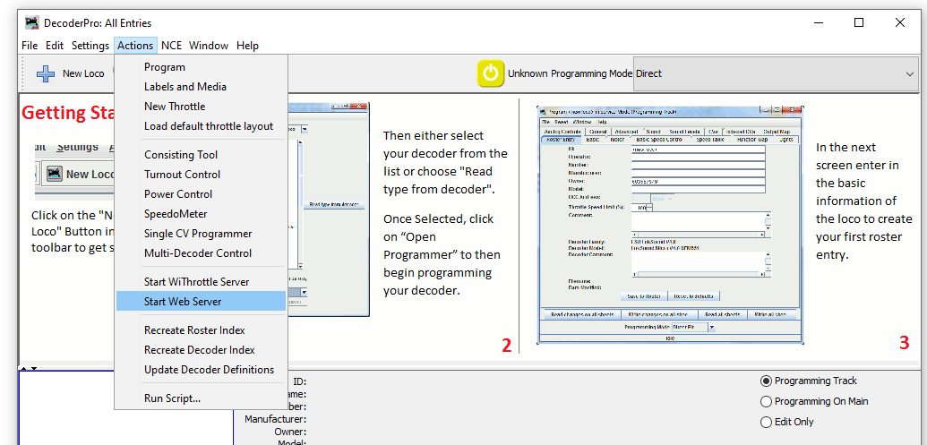
To start a web server with JMRI open and connected to the NCE system navigate to Actions>Start Wi Throttle Server
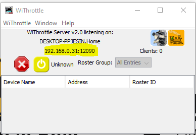
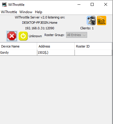
You’ll see this window note down the IP Address and port number (highlighted in yellow). In this example the IP address is 192.168.0.31 and the port is 12090. This IP address is internal to your home network, don’t panic your router firewall will prevent access to anyone from outside your home gaining access to your layout.
Now JMRI is running and allowing any device with WiThrottle or Engine Driver or any other supported app to connect to your computer and through it the layout. So lets in this example use the Android app Engine Driver.
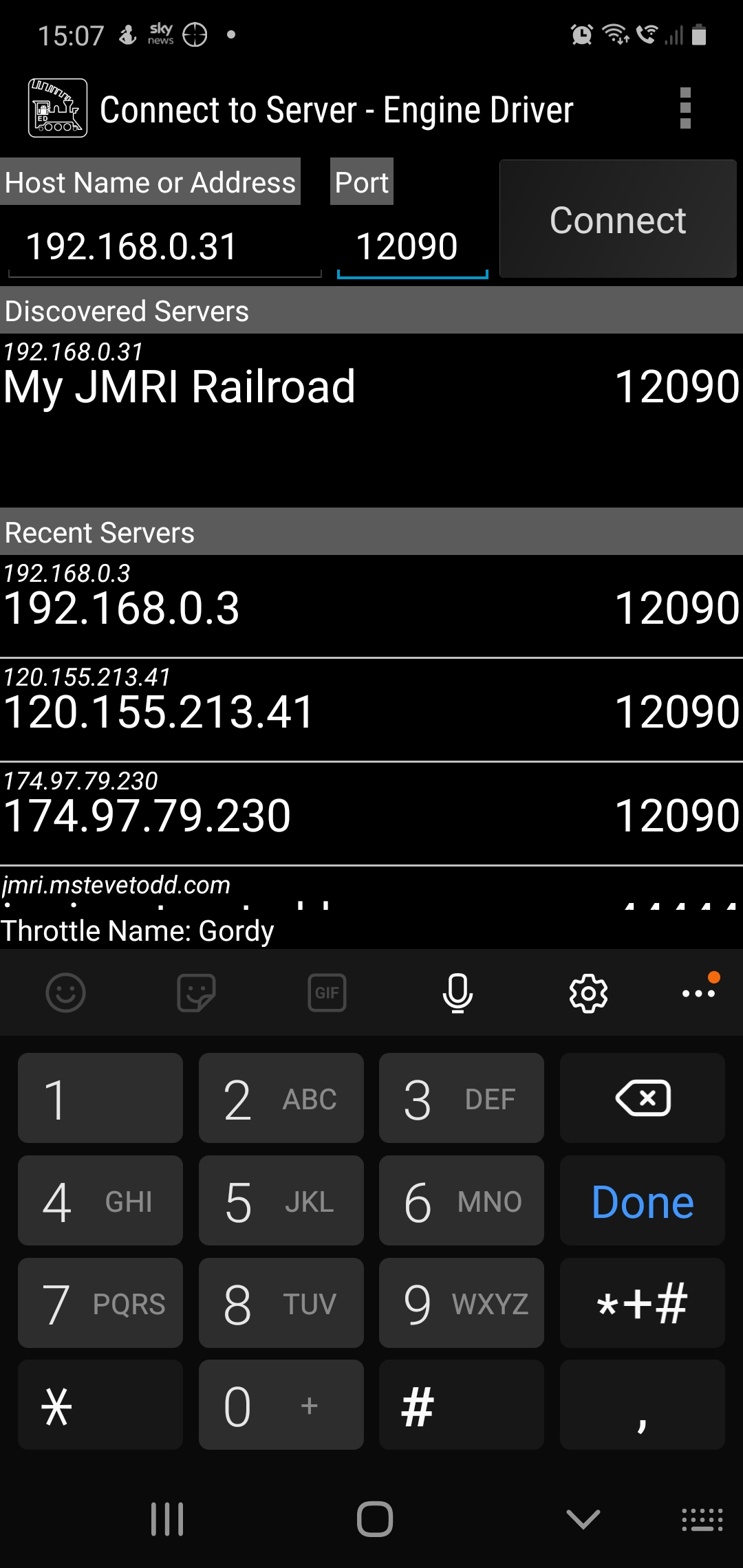
When opening the app your device will either have found the server or you can enter the IP address and port number at the top as shown above. Hit connect and then you should be able to aquire a locomotive on your layout. If you have entered your roster into JMRI then you can see all locomotives in your roster rather than entering the DCC address.
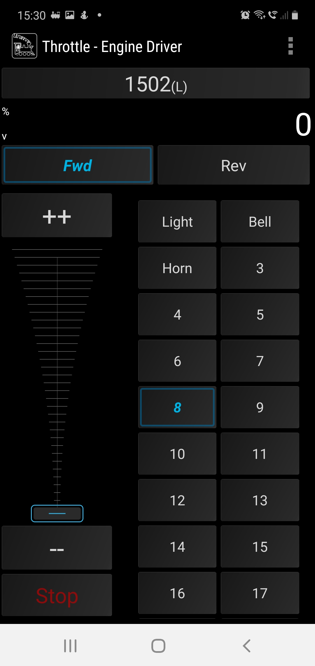
Engine Driver Throttle in Dark Mode, the loco is selected using its DCC address 1502
Back over on the PC we can see how many wifi throttles we have connected on the WiThrottle screen.
This is a great way to add more throttles to your layout and to the basic NCE PowerCab system which limits you to only having 4 cabs.
I hope youhave found this useful, its not a huge step from here to remote ops so we’ll cover that in a future post.
For now, stay safe and keep working on your railroads.
This was supposed to be a nice easy post on a Friday evening followed by a beer or ten. However as with most things electronic its not gone quite to plan.
So what are we attempting to do? well in order to have the layout run from anywhere in the world it needs to talk to the computer and the plan is to do that using JMRI and a USB interface. Its usually simple and I have done this on my other layout before with no issue. Not today it would seem but anyway lets talk about the process.
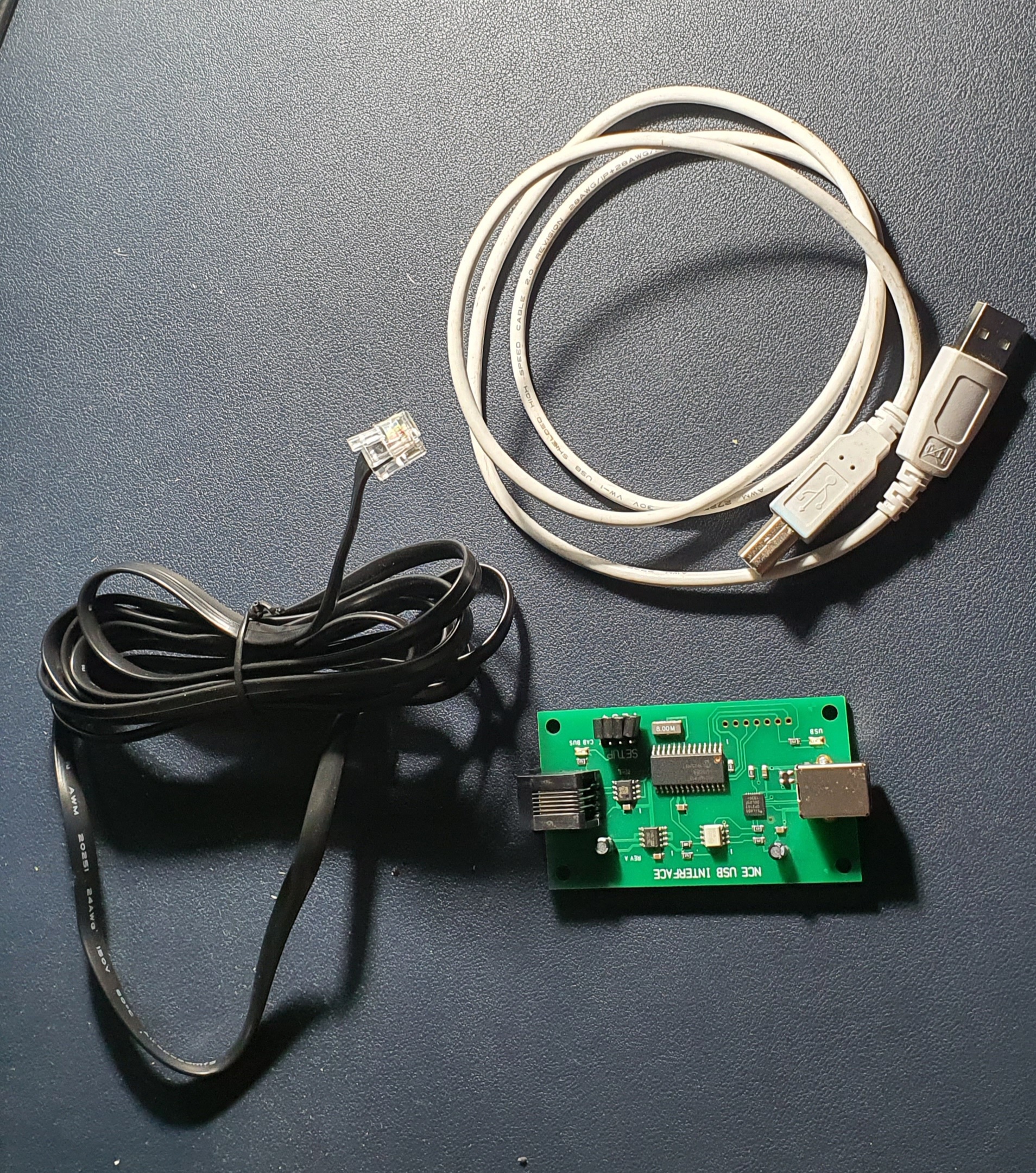
So this is what you need to interface an NCE powerCab to your PC. Its a standard NCE Cab bus cable, a NCE USB Interface and a USB A>B cable like you use for hooking up a printer.
To set up power up the Powercab and then plug the NCE USB Interface into the spare Cab socket and you should be able to detect the device when you plug it into your PC.
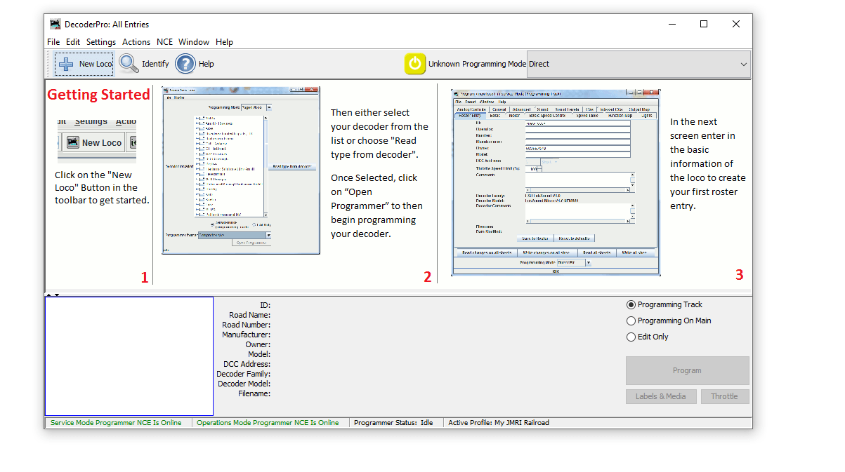
When you open JMRI you will be asked to set up connections if not go to Edit>Preferences and you’ll see connections at the top
Select NCE as the Manufacturer and NCE USB as the system connection. Its really important you select the correct COM port, if you don’t know which one to use then go to Device Manager on your PC (if windows) and find the ‘CP210x USB to UART Bridge’ thats the NCE USB device look for the com port and make sure this matches in JMRI. Save your settings and exit.
When you return to the Decoder Pro screen you should then see the two green indications at the bottom of the window. If like mine did for the best part of an hour these go red and are not connected after a few seconds but are green to start with go to JMRI downloads and update the version on your PC. Then un plug and start everything again. If its red and never green check you have selected the correct COM port.
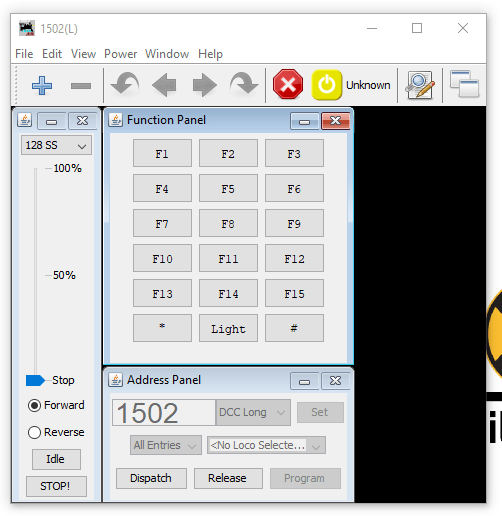
Then to test you have control of the layout go to Actions>New Throttle you’ll get this window
JMRI Throtle Window
Select a loco on your roster thats on the layout by entering the address in the Address Panel and click on set. This will aquire the locomotive. Then see if you can use any of the functions if a sound loco Horn is always a good one to test. If thats all working then you are set up and ready to go. You can either go to the next stage and use Wifi throttles or even allow remote ops or program your locomotives..
We’ll cover the JMRI Web Server for WIFI throttles and also Remote Ops in a future blog post.
So the electrics are pretty simple here but its still worth blogging about. I guess its an improvement on the how to drill a hole post. Anyway back to it, lets get on with it, so we have a stick with a length of track on it and a DCC bus to connect it into. The thing is removeable so our project needs to be removeable as well.
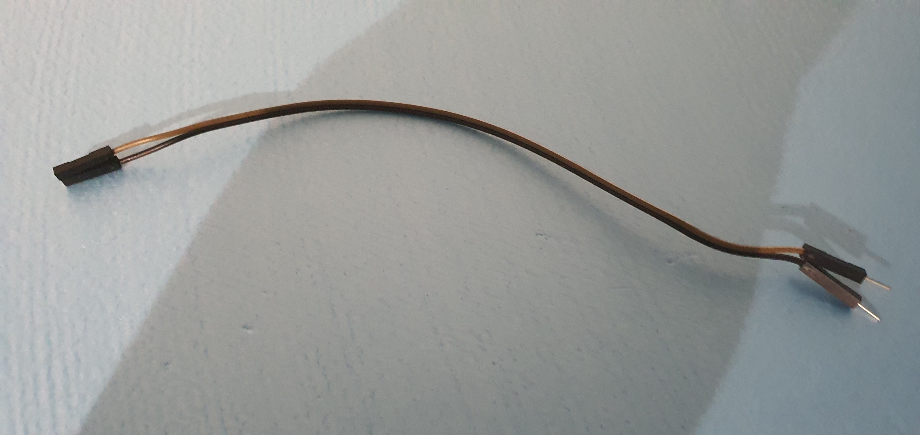
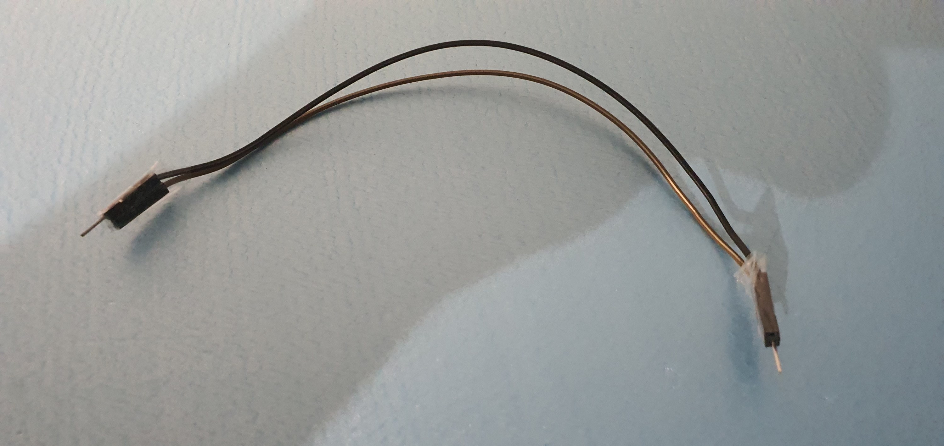
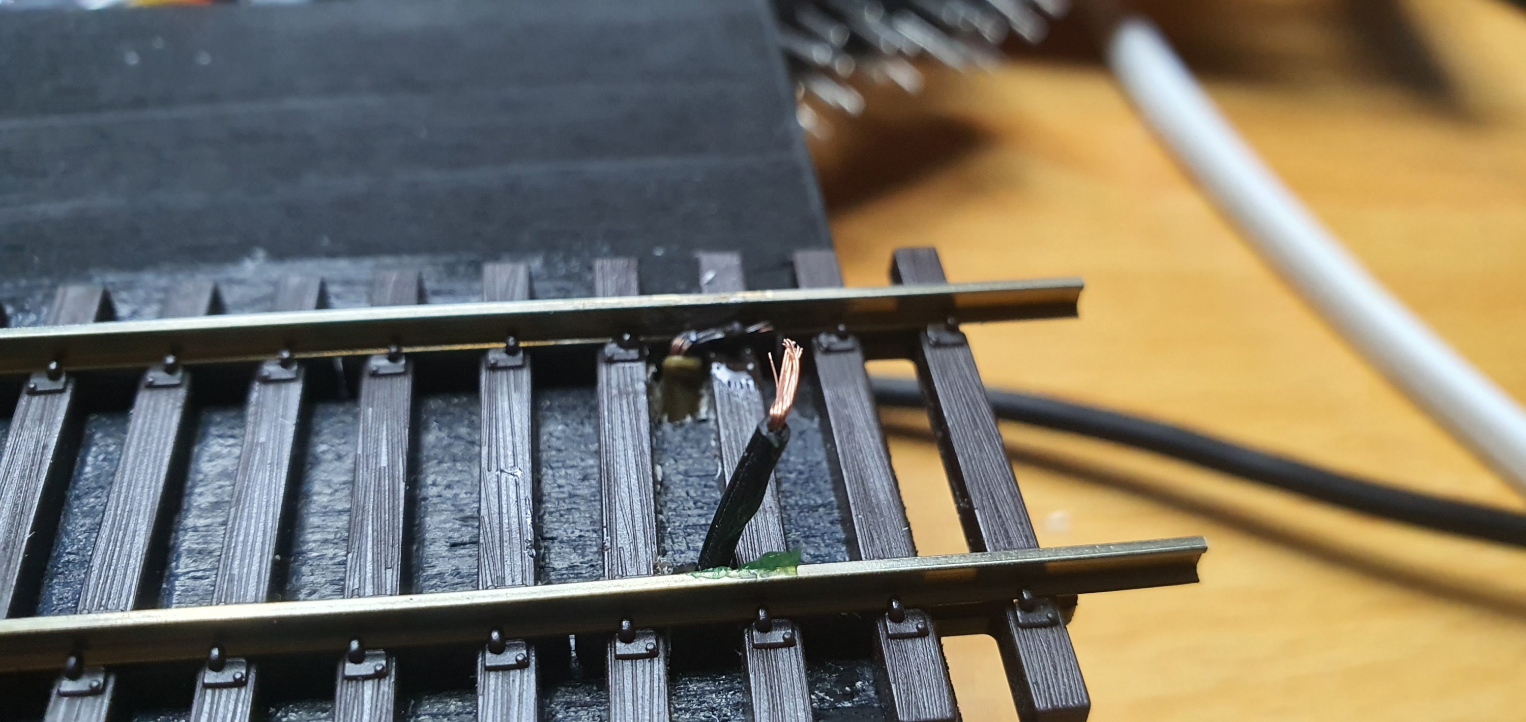
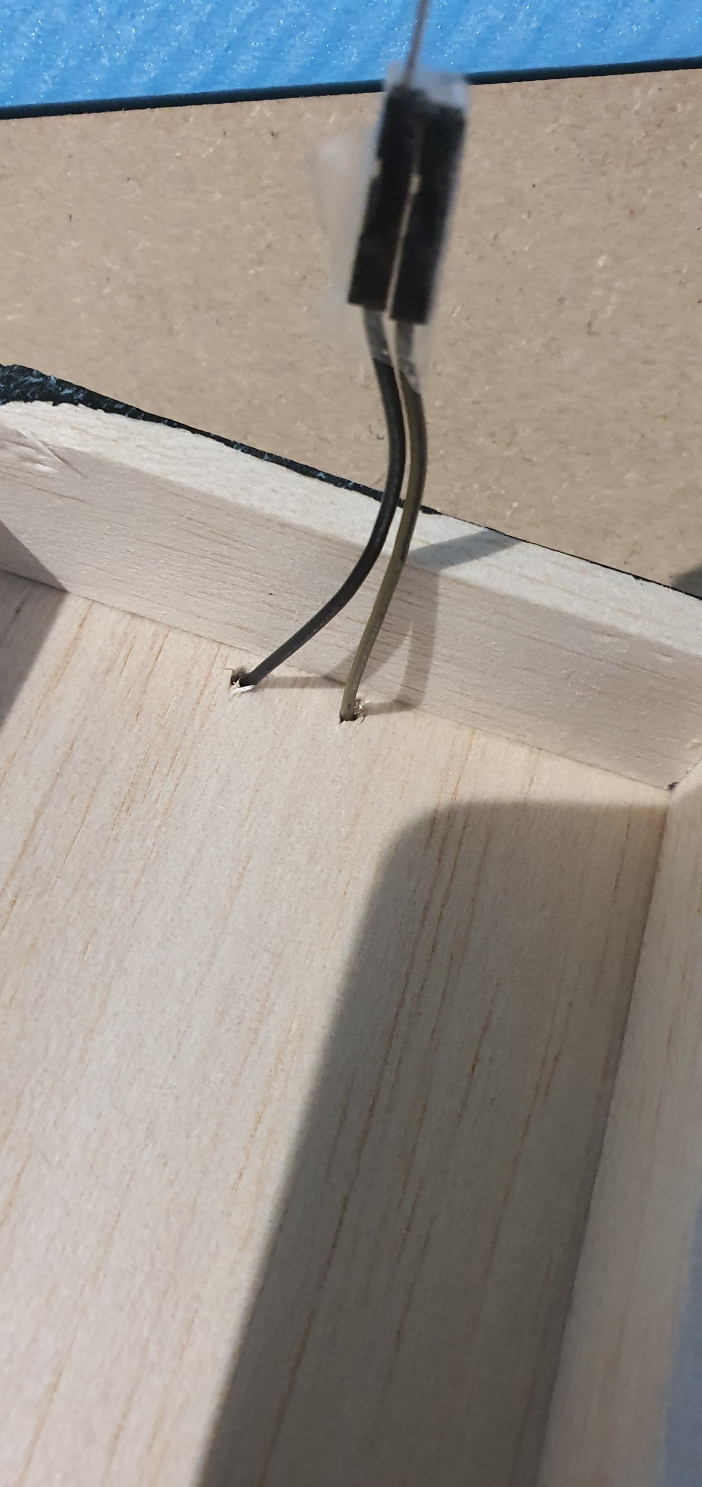
As I have said a hundred times due to our lockdown restrictions I am well down on materials and don’t have a spare power pole connector. ah! not a problem here is the poor mans solution. Take two male female hook up wires turn one around tape them together and you have a power pole connector. Lets look at how to do this.
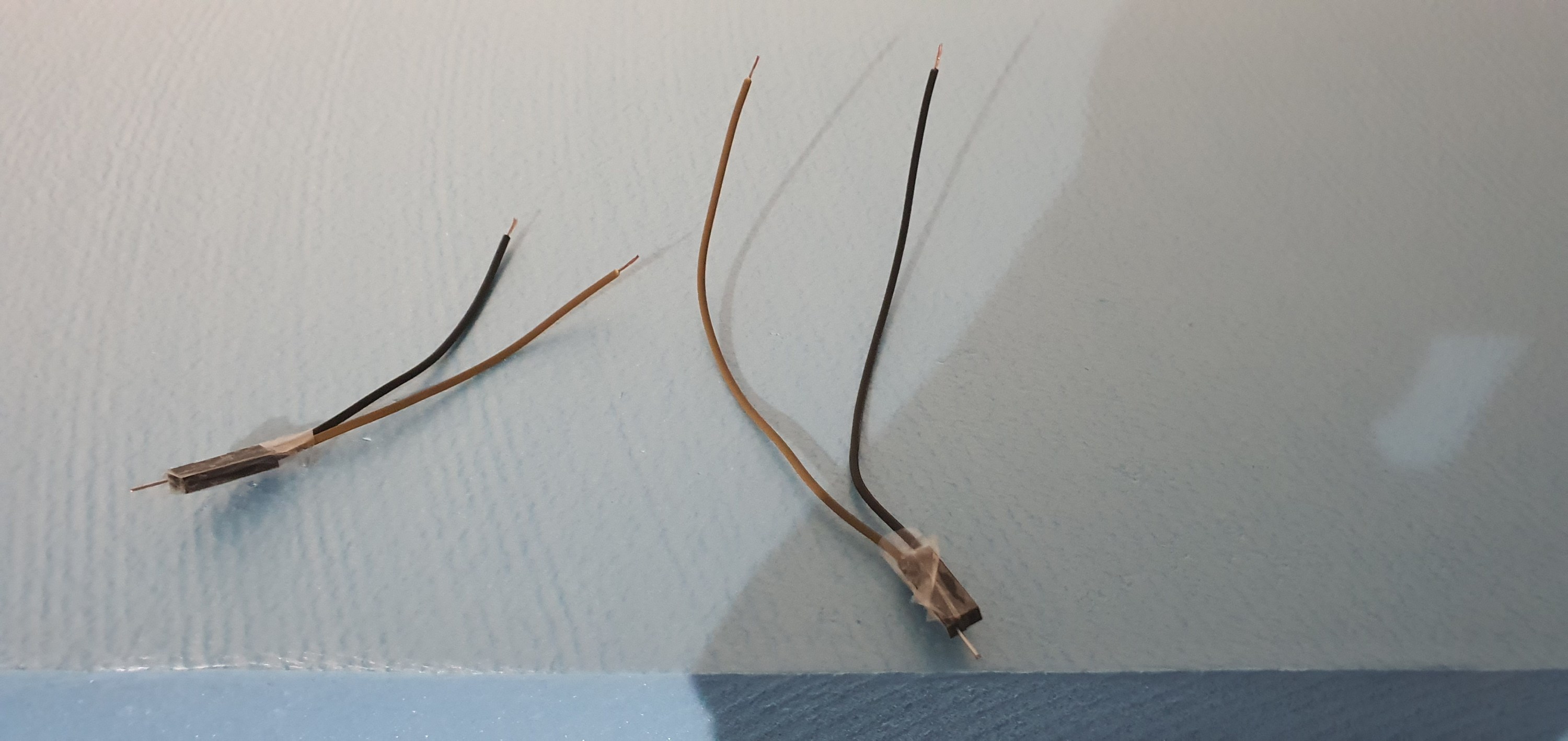
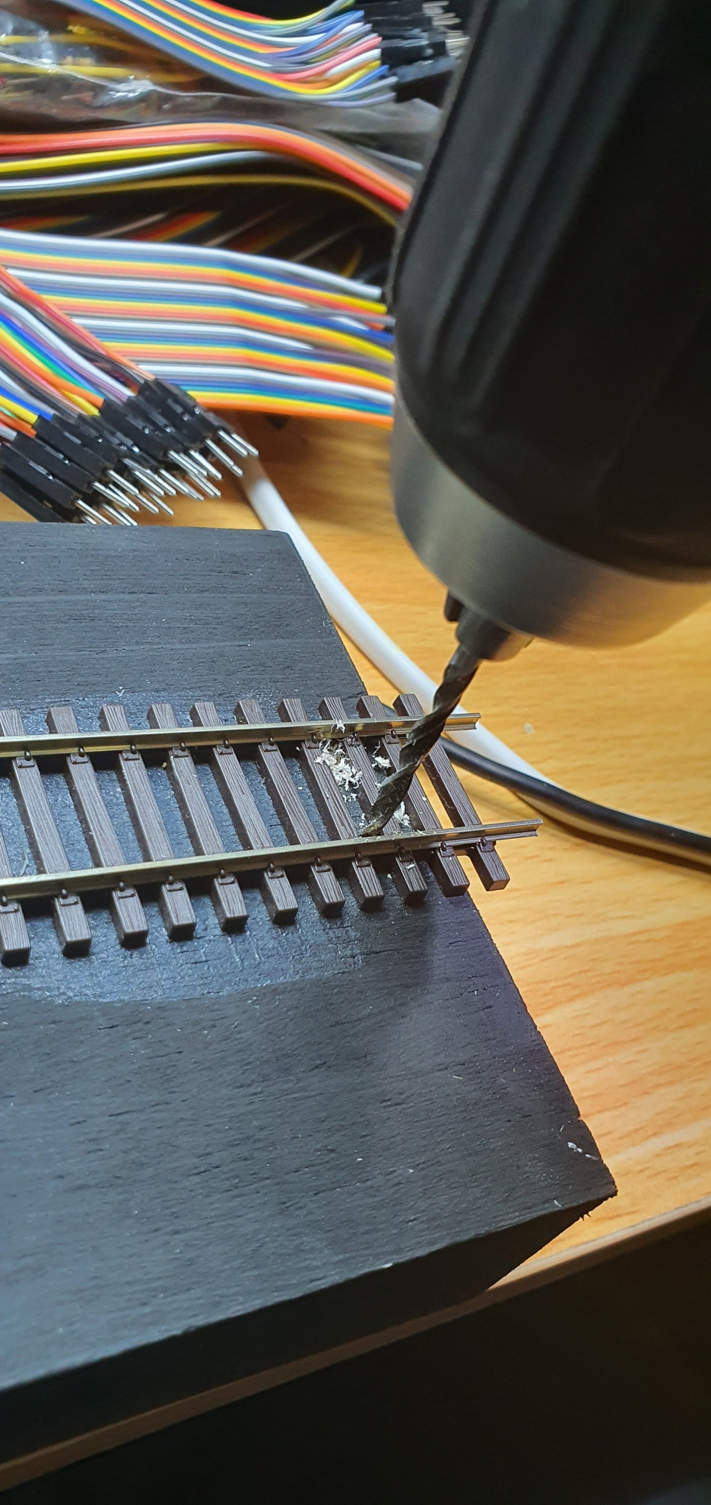
Hook up cables as they come, you get them with Ardunio sets or from AmazonTurn them around and tape the ends together cut them in half and we have two plugs for pennies – perfect eh! drill a hole for your wires to goput the wires in from below bend and tin them then solder to the inside bottom of each rail there we go one plug fitted fit the other plug to the DCC bus and we are done
A quick test
All looks good to me 🙂 storage
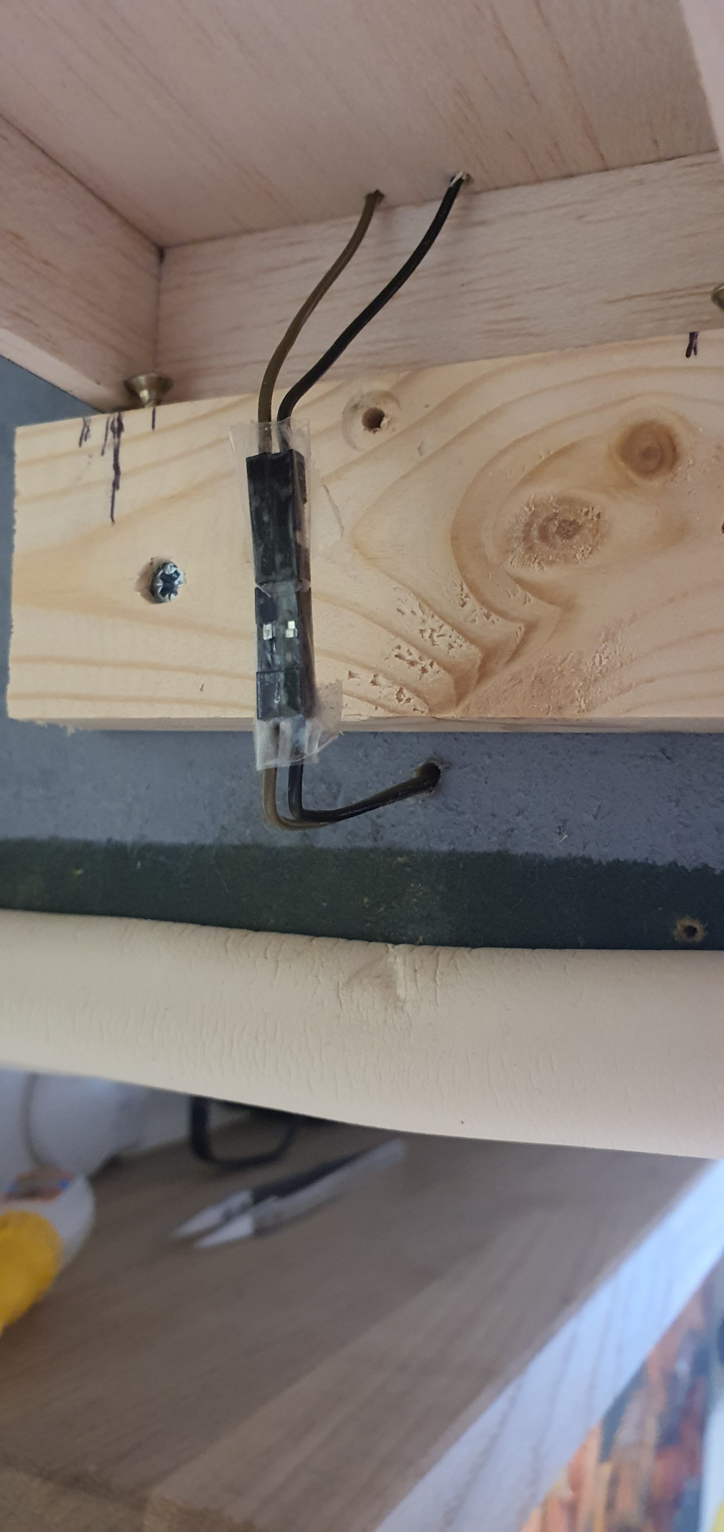
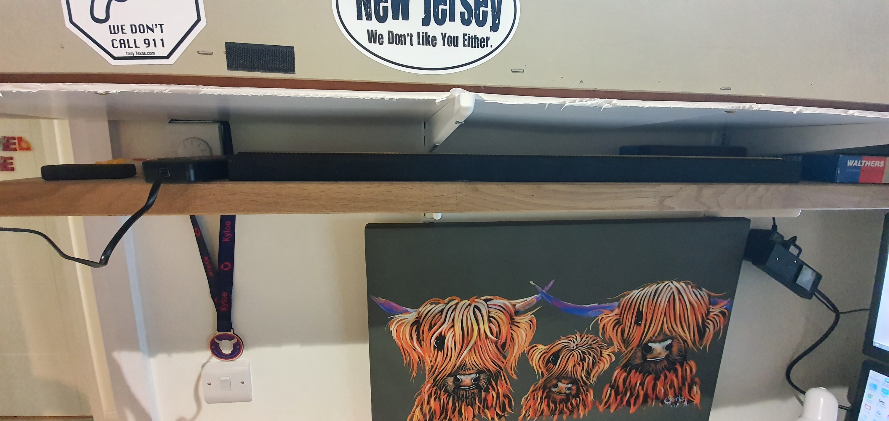
This really is a low profile solution the plank neatly fits below my layout on a small shelf that also holds some stock and the controller when not in use.
Thats it we have a working switching stick. Next up is the connection to the PC and some remote op sessions.
Now we need to add alignment screws and actaually get some track down on the staging stick.
Alignment
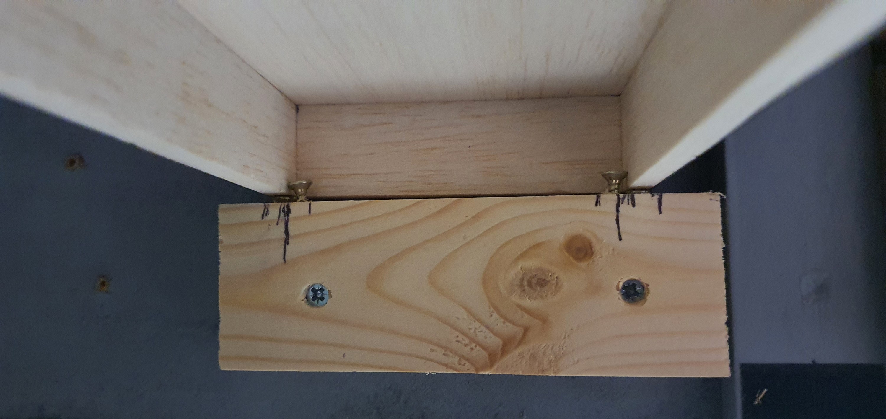
This isn’t difficult and really needed only four screws. Two of the screws are used to allow adjustment up and down of the staging plank at the layout end. This allows for the vertical alignment to be altered and adjusted as required.
You can just see them in the above image below the structure of the staging plank. The two screws inboard of the vertical alignment screws are to ensure horizontal alignment.
Fitting the track
With the track placed on the staging plank I could test the vertical alignment before applying glue to the hold the track in place.
At this point it was vital to check alignment both on and off the staging plank to so this I just used a freight car and kept adjusting the vertical alignment screws until there was no derailment in either direction or noticable movement of the car.
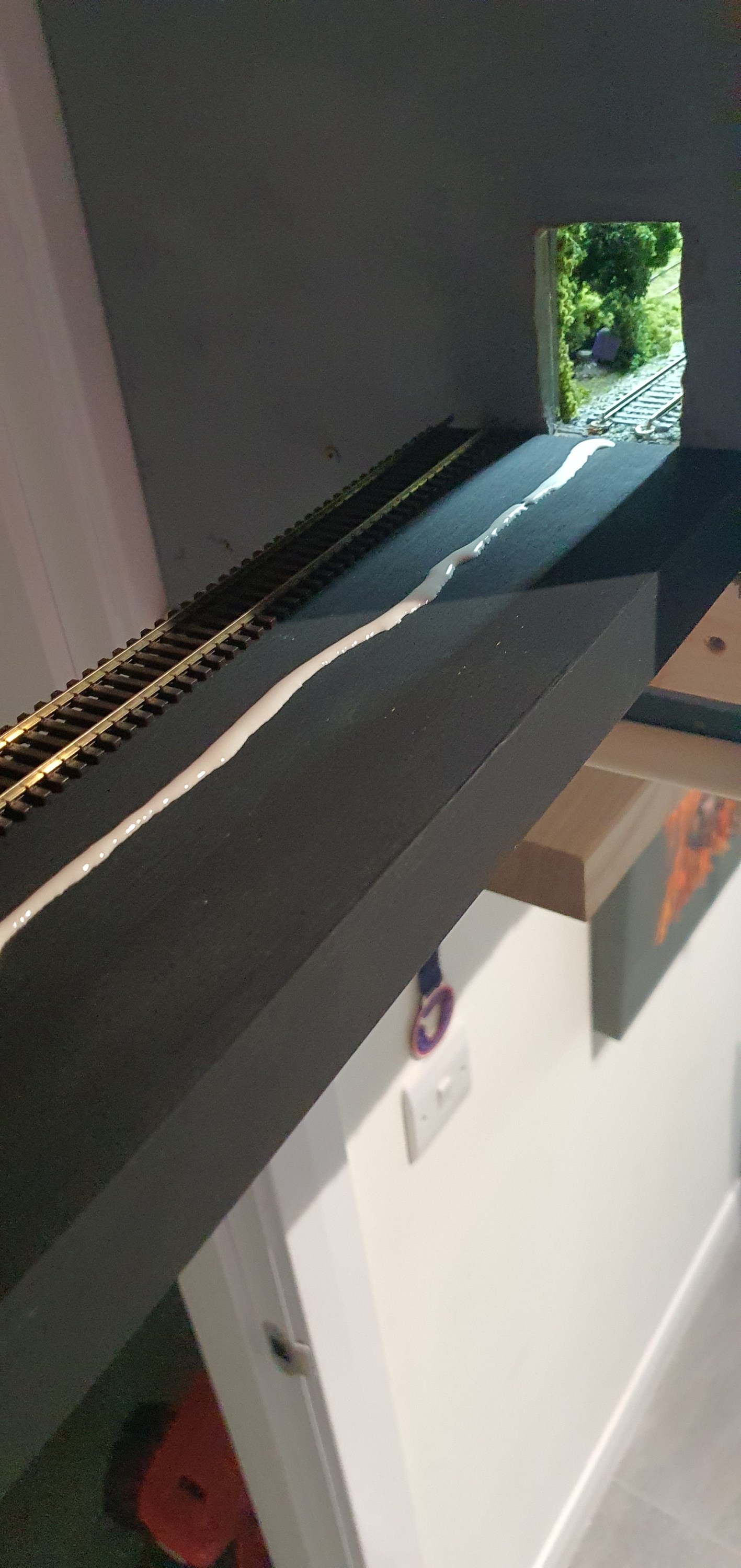
With everything appearing to run well it was time to glue the track down. This is really very simple but the basic rules of track laying apply. first lay a bead of glue along the length of the flex track not side to side, I used Gorrila PVA glue for this. Then before laying the track smooth the bead out to a flat strip of PVA glue.
Then it was time to lay the track ensuring horizontal alignment of the track and then gently pushing the ties into the glue. I like Gorrila glue because its tacky enough to hold the track in place almost immediatley but allows you to re-position some cheaper PVA glues have water added which means track will move until the glue sets so be careful. Align the track horizontally and re test before the glue dries.
Thats pretty much it you should have something that looks like this. If we were using Power onboard we would be done at this point but we are not so we’ll look at some simple electronics in Part 3 of the staging plank.
We’ll get to that in the next few days as we prepare for remote ops on the switching layout.
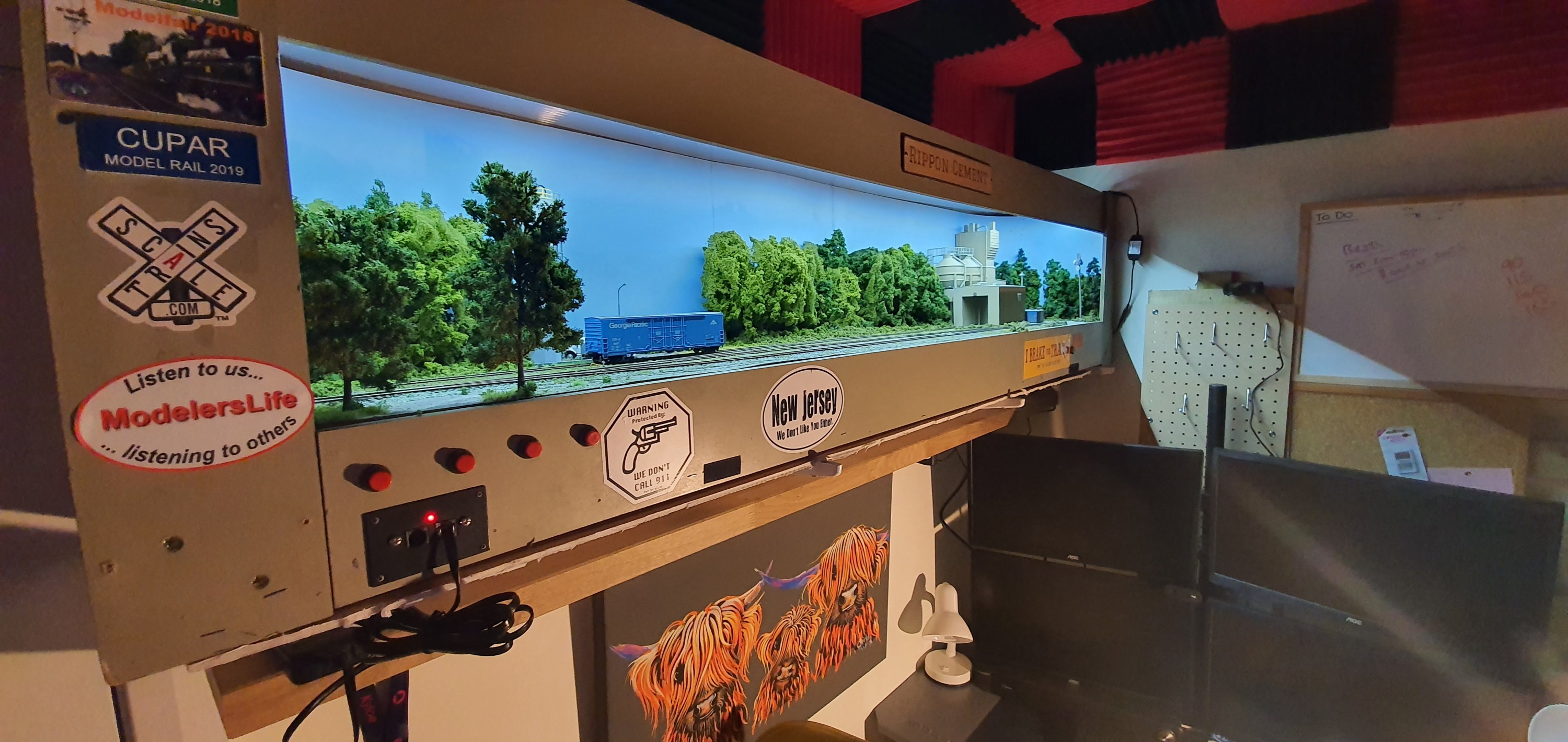
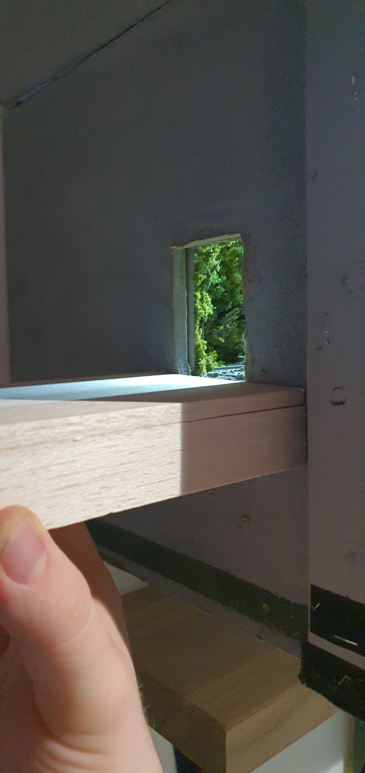
Ripon Cement in the home office the entrance to staging is off the left hand end of the layout
Ripon Cement has to have a staging track extending off scene in order for the operator to run around the layout and access the spur to the cement plant itself with more than just the locomotive.
There is space at the left hand end of the layout for a staging track, however we have to cross the doorway. The door into the room opens inwards and so a staging track across the doorway is needed but the door will have to be open. The next challenge is that I can’t trash the door!!!
Ok so lets get the door open and measure, well we have 82cm between the end of the layout and the door. You’d think I had planned this eh! as thats a locomotive and about 3 cars which is the perfect max length of train for the two industries on this layout. There are 3 car spots and 2 off spots on the layout so if at capacity and you bring that upto 8 cars plus a locomotive things can get very busy really quickly. Of course every train doesn’t serve every industry so most trains are going to be smaller than this.
Layout Designer Iain Rice, designed a over door staging track for a vertical switching layout on Ikea bookshelves. Just like the home office layout which will at some point be re-united with its other cousins to form the industrial branchline I had at my previous home. however, for now we only need to concern ourselves with a single track that can be removed quickly and easily with minimal damage to the layout or door.
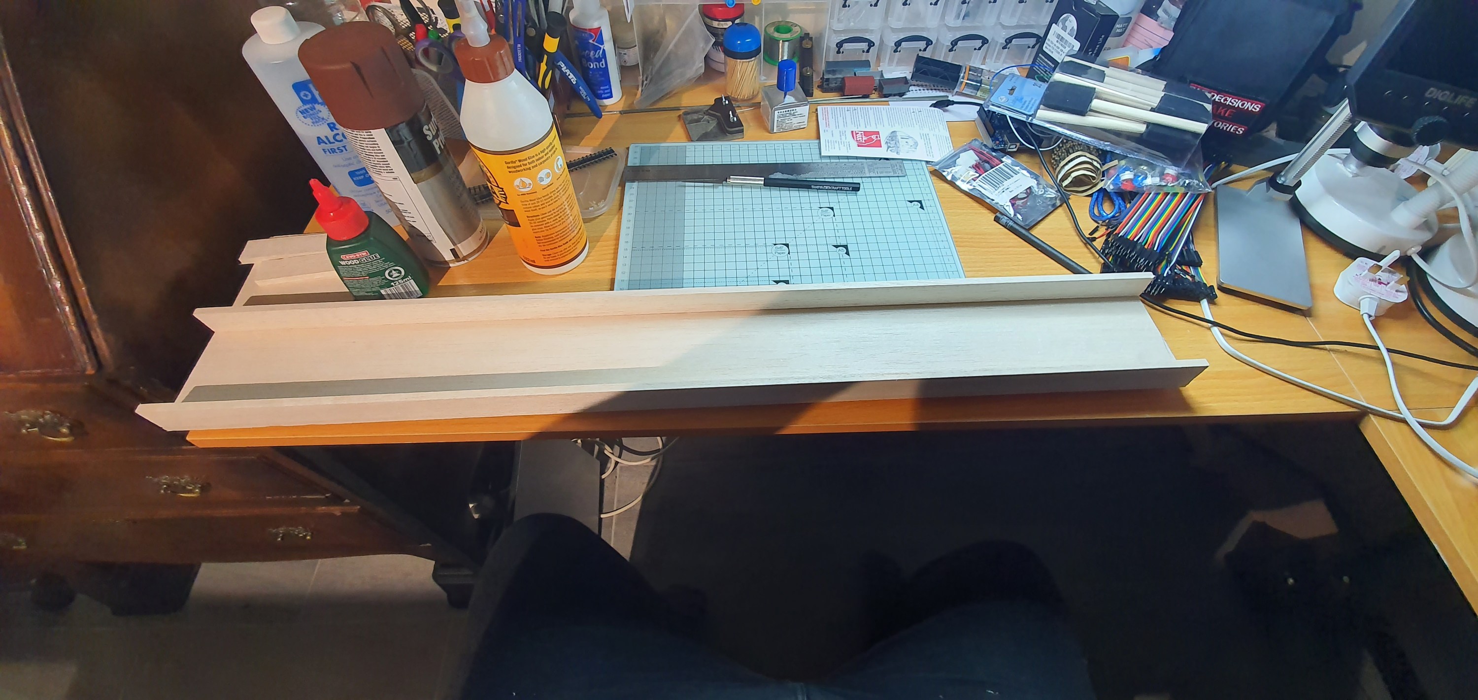
Right ok! first we need at least a plank to hold the track. This needs to be strong but lightweight, remember we don’t want to construct a monster support and strain the layout or door. You always have some stuff hanging around from other projects right, well I had some Balsa wood. Three lengths of 25mmx6mmx914mm and some 100mmx6mmx914 so that would make a really nice solid support for the length of flex. It wouldn’t be too deep either so when in place would just be a nod under to get out of the room.
I cut two of the smaller strips and the wide strip down to 81cm in length. Using Deluxe Materials Speed Bond I just glued these together and added cross pieces at each end and in the centre giving 4 in total. I squared up the little box and made sure it stayed in place with small clamps. Flipped it over and added some weight while it glued. Its called speed bond for a reason after only an hour this was solid enough for paint.
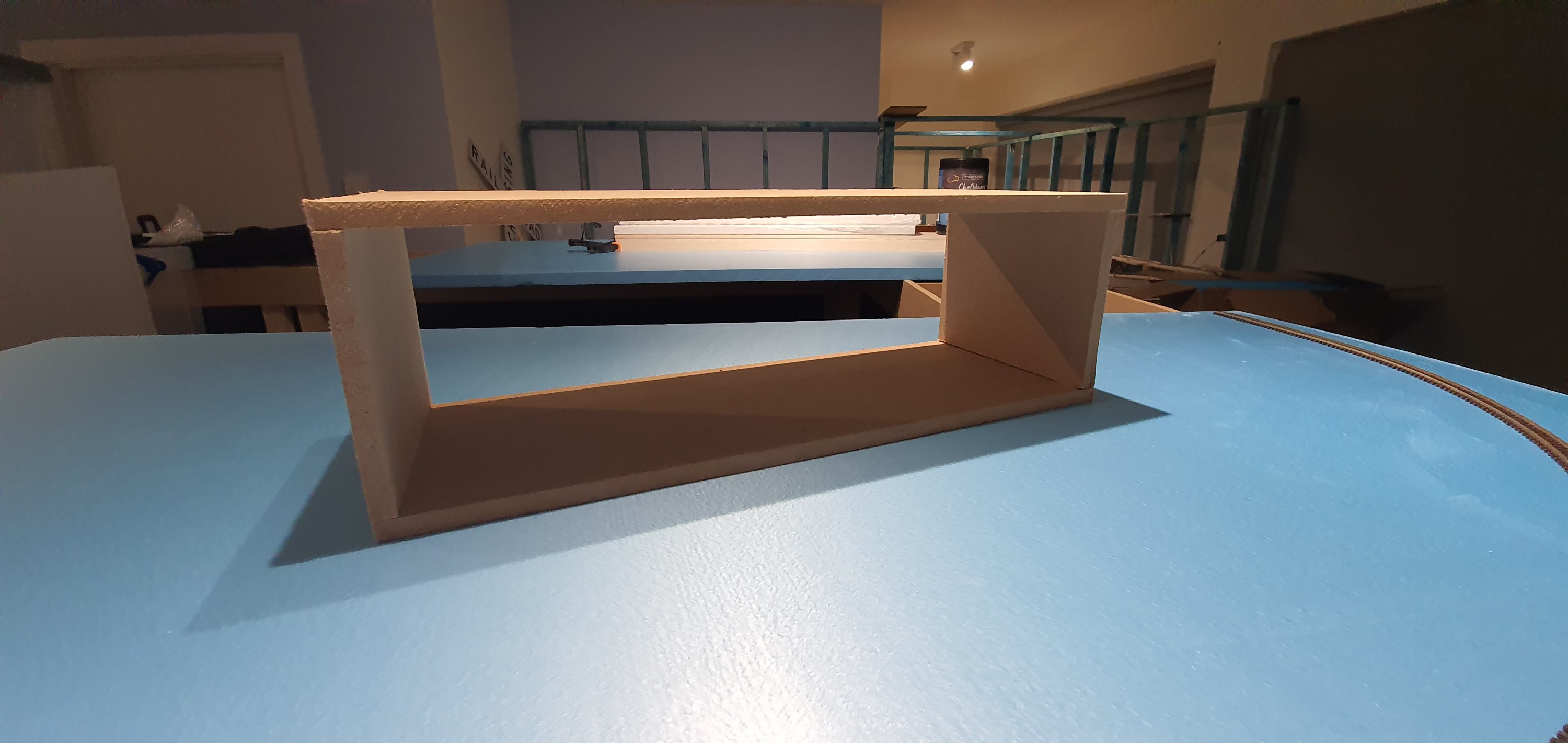
Ah thats the easy part done then. Now for the door support. Fortunatley when the baseboards arrived for the Waukesha Sub just before Christmas they came with a bit of packaging that held the screws and bolts for assemble of they modules. Whilst this was just scrap MDF nailed together to form a box with a centre divider, it was perfect for my plank to fit into. So it was quickly deconstructed it and the centre divider was adjusted to hold the plank at the perfect height when hung over the door. A wee bit of glue and 2 mins with the nail gun and we had a nice support with 100mm sides that would prevent anyone knocking the plank off its support and turning my loco & rolling stock back into kits.
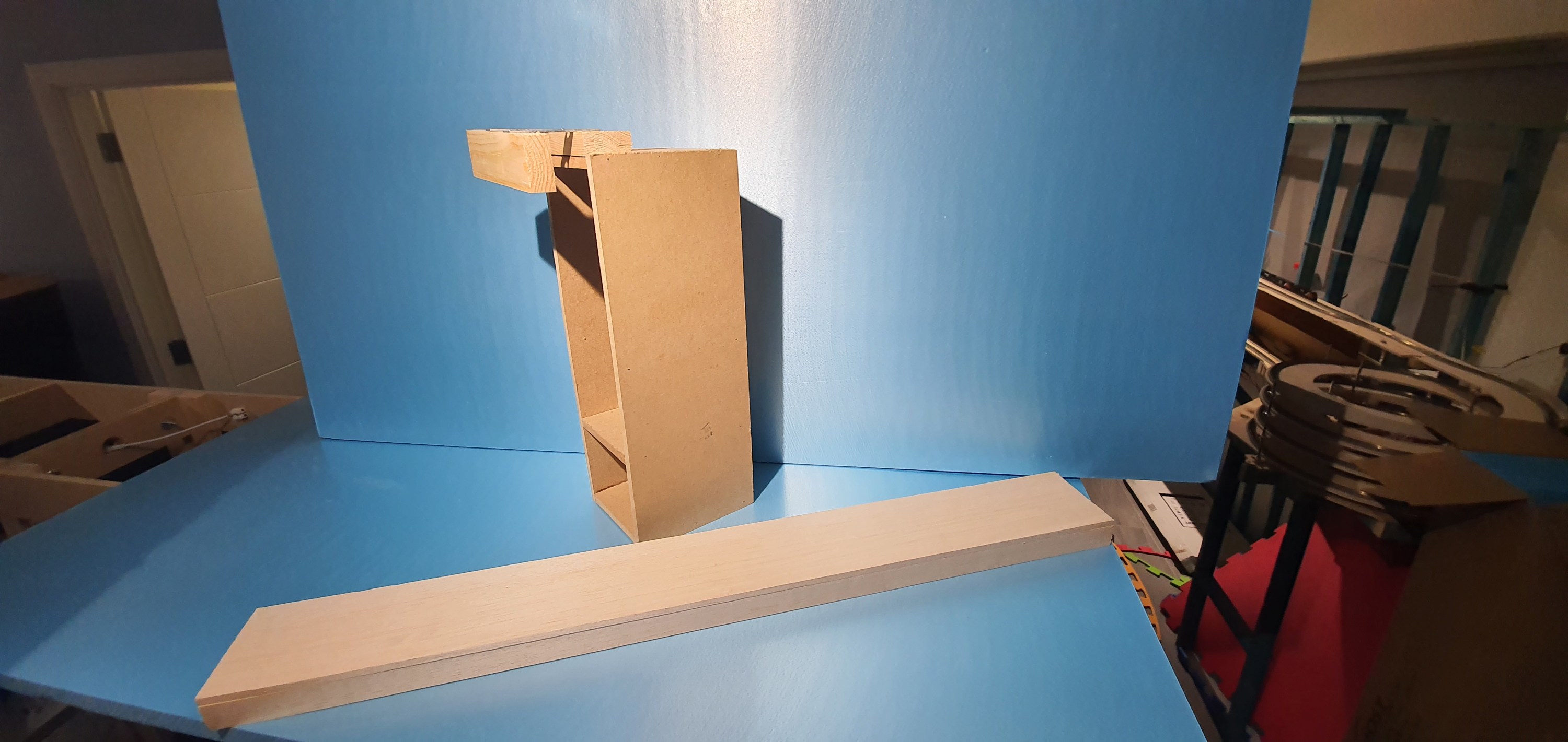
For the hook to hold it over the door I attached a piece of 2×1 to the top of the box and using some metal strips I secured another piece of 2×1 to the rear that would touch the door on the otherside. At this point glue and nails isn’t going to cut it so this whole section was attached to the box with 3.5x30mm screws and some glue, every little helps right?
Plank and bracket ready for test fitting
Perfect now lets get this in place and see if it works.
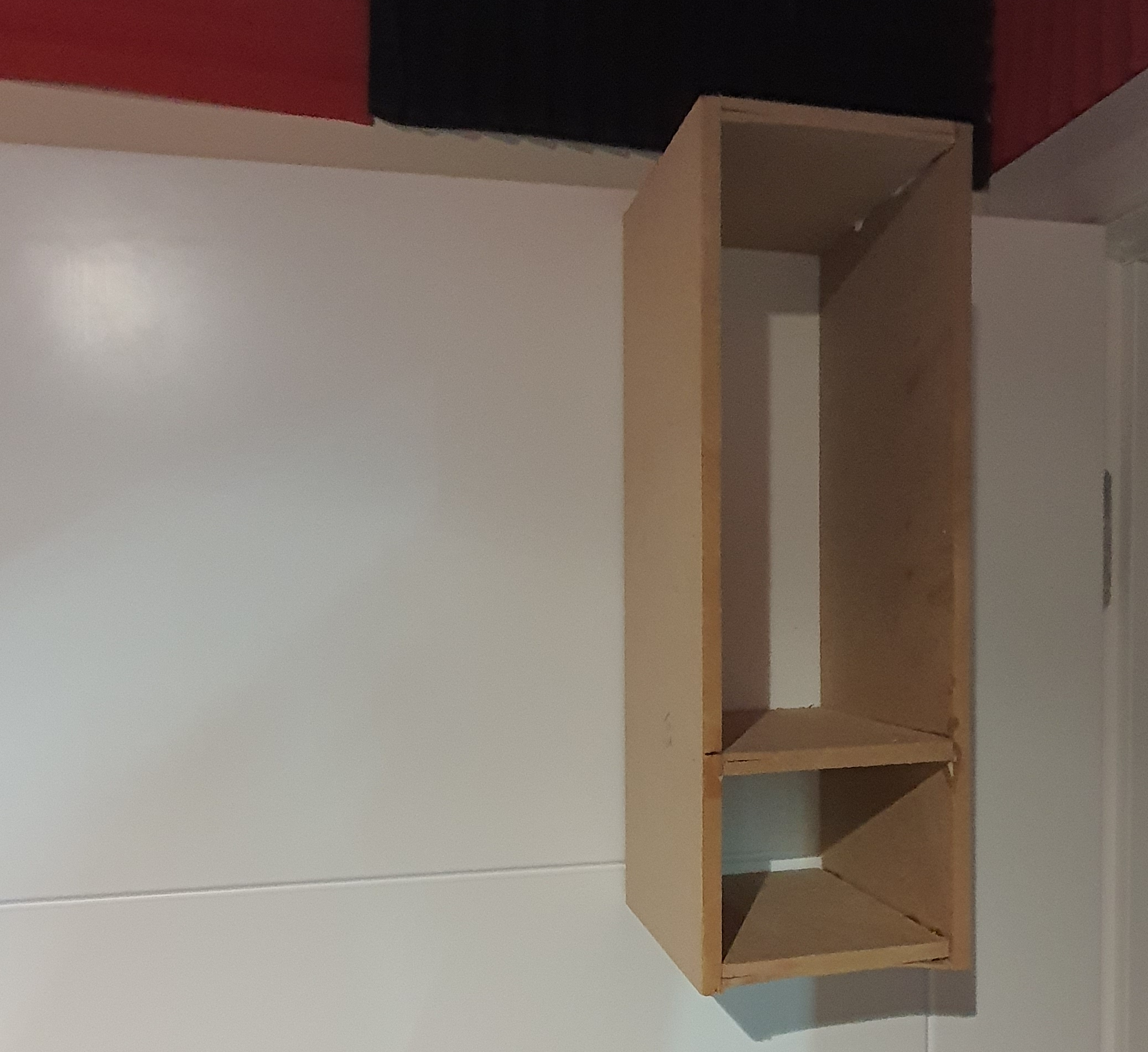
With the plank in place I could measure where I would need to add the 2×1 support on the layout end in order to hold the other end of the plank when in place.
Looking great eh! I added a couple of screws to the top of the 2×1 to hold the plank in alignement and prevent it from being pushed off if hit. To remove it you have to lift vertical so care will be needed when you are nodding under the layout.
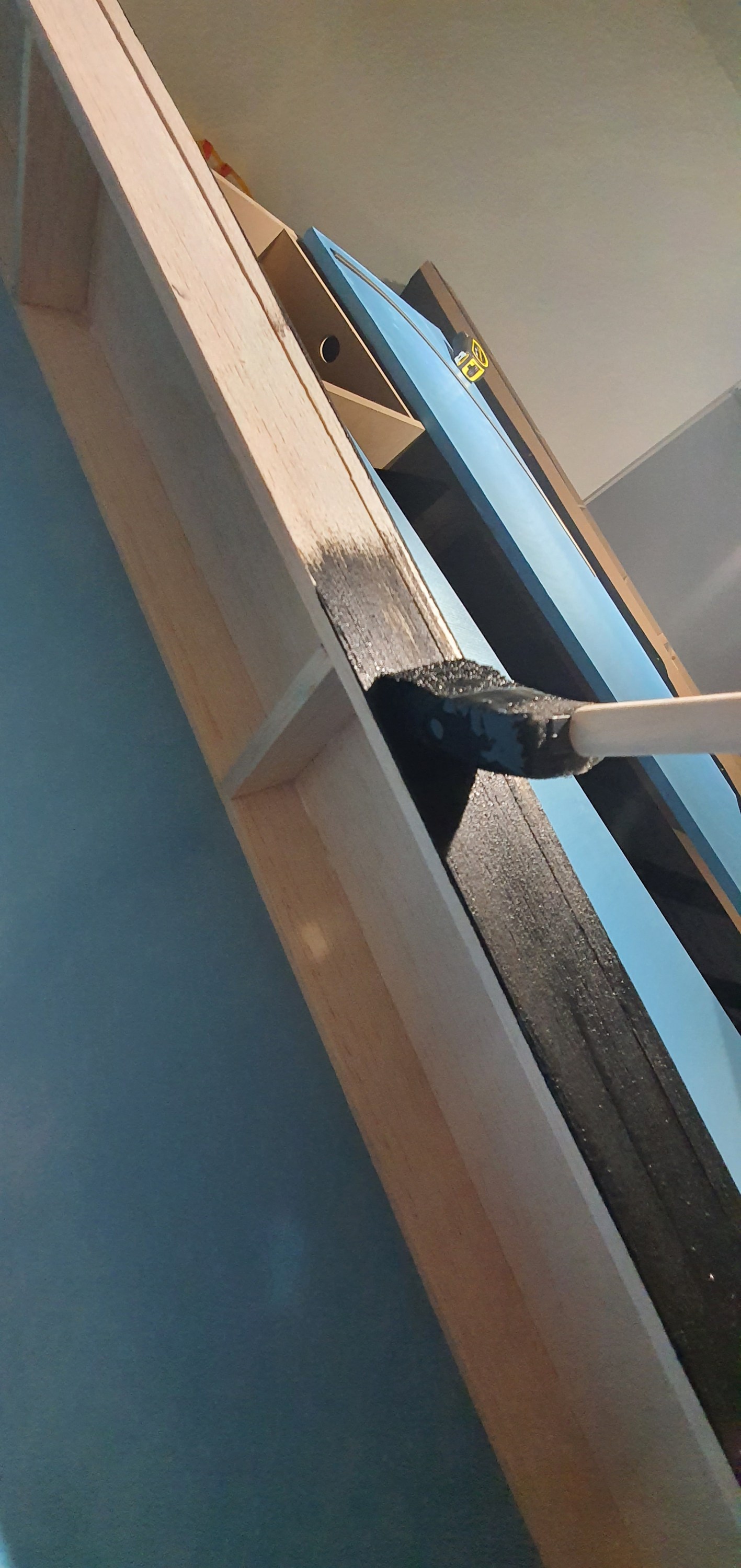
All that was left to do in the part 1 was paint. For this i decided to use Chalk board paint. It is a one coat and done deal, so super quick but is really thick when it applies. It dries quickly but I left if overnight to dry, in our next installment of the switching plank we’ll be adding the track and some wires with removeable connectors so we can start doing some operations.
yeah that really is just one coat of the treacle, sorry chalkboard paint on to the Balsa.
Rippon Cement, has been my layout to take to train shows for the past few years. Its a HO switching layout built by Chris Gilbert orignially as Florida Springs. It has a page on my website here if you want to see more information. https://gordy.uk/my-layouts/rippon-cement/
As the benchwork is now in place for the Waukesha Sub Division, my work benches have re-located below that layout. Freeing up the room that was my workshop to become my home office. Its quite a small room about 1775mm x 2800mm and currently has a desk for my paid job and my personal desk so quite a squeeze but its big enough for me and Dabber. His dog bed just slides beneath which ever desk I am not working at.
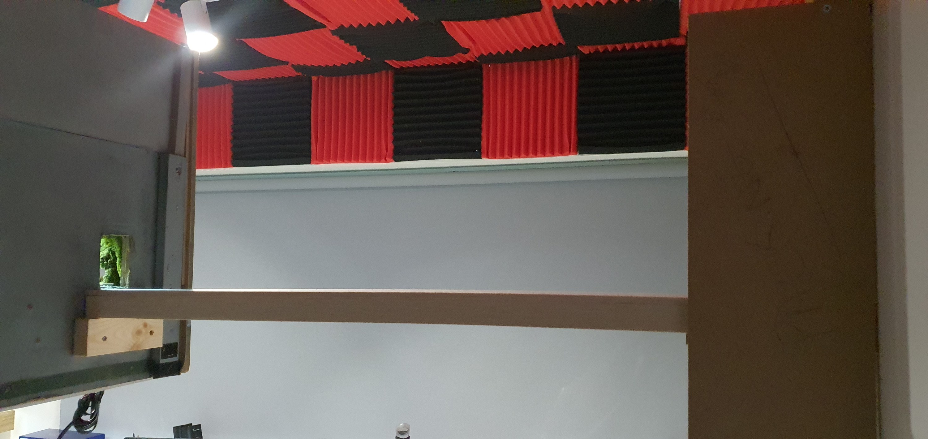
Its a squeeze in there but at 170cm high Rippon Cement clears the monitors of my personal computer.
As the whole train room is filled with the Waukesha Sub there was no room for Rippon Cement and if you look in some images of my benchwork posts its leaning on its end looking very sorry for itself. It had also sustained some damage during its move up to Orkney so I didn’t realy want to risk anymore. So what to do. Well as I am 183cm tall I knew a layout at eye level for me is about 170cm above the deck. A quick check with the tape measure showed that Ripon Cement would fit along the wall with the door into the room and at that height would clear my 4 monitors of my personal comupter and when I am not working from home – Covid cannot last forever!!
I can mount the other two levels of the multi deck switcher here at more sensible heights but for now I can at least run some trains when I get the urge whilst the Waukesha sub is under construction. Next to be overcome was lights, power and somewhere to store the stock when not in use on the layout. Ah well a quick replacement LED strip fixed the lights damaged during the last train show outing.I also found a spare but perfectly sized piece of oak worktop from the constrution of our house that I turned into a shelf fitted tightly below the layout at 160cm high. Remember I have to sit under this thing without knocking myself out!
You can just see the narrow stock shelf hiding here below the layout.
So layout up, power and lighting sorted. But erm Houston we have a problem there is no where for the trains to run so that will be the next project, Utilising the office door to support one end and the end of the layout to support the other. Its something Iain Rice suggested to do in one of his small track plan books. I’ll share how well that works out in another post.
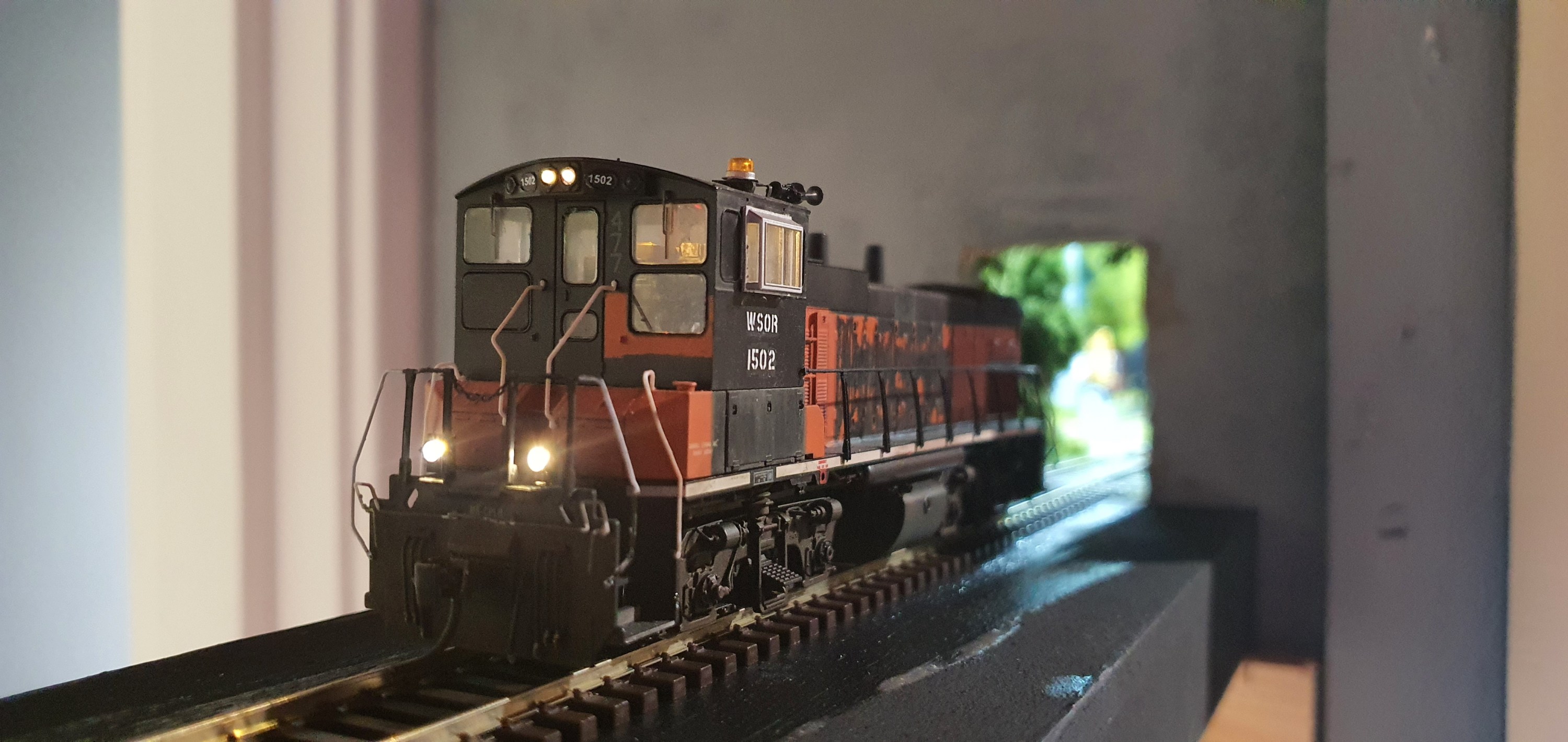
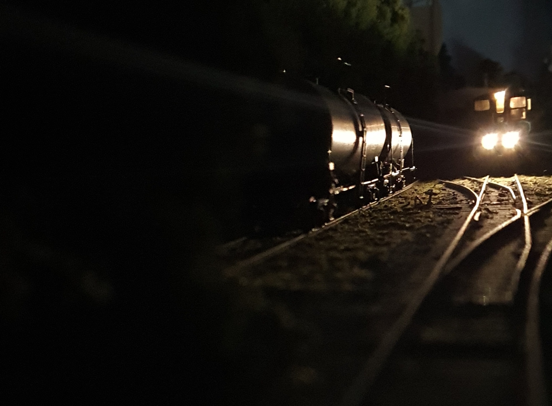
In the meantime enjoy a few arty shots taken with my smart phone on Rippon Cement.I guess that train is ready to leave so I best crack on with giving it some place to go to.