Well this weekend we should have had the largest train show in North America at the Eastern Exposition Center in West Springfield MA.. However thats just not possible with the current restictions in place. I have been lucky enough to attend the show in 2018, 2019 and 2020. Infact it was my only train show in 2020 so I was very fortunate.
The folks at the show and the vendors have worked with Virtual Railfan to put on a virtual train show today and tomorrow. I reccomend tuning in even if you haven’t or never will be able to attend the real show in person.
Well we have been doing these events now for 9 months and they just keep getting better. I am glad there is such a good team running these events which just wouldn’t happen without Brac, Martyn, Speed, Andy, John & Brooks and our cast of clinicians. If you missed the live shows you can still watch them on Youtube.
We previously looked at modifying the Elfa twin slot uprights to add an additional screw hole so that we can use them to support the upper deck, back scenes and eventually the lighting for the layout. The uprights will be fitted at 600mm intervals meaning i need 33 in total. However I was only able to get 11 of these from my supplier, I am hoping to get the remaining 22 shipped to Orkney by the end of this week.
modified upright next to a unmodified upright
With only a limited number of uprights it made sense to work on the hardest to reach areas first. this means working in the area marked in red on the plan below. As the layout is modular i was able to remove the left hand 4 modules of the layout and the intermediate module on the right hand side before moving the whole section againse the wall out to enable access to the rear. If you were not concerned about damage to the wall of course you could just ignore my step and screw the uprights straight to your wall.
So lets get on with getting these things fitted.
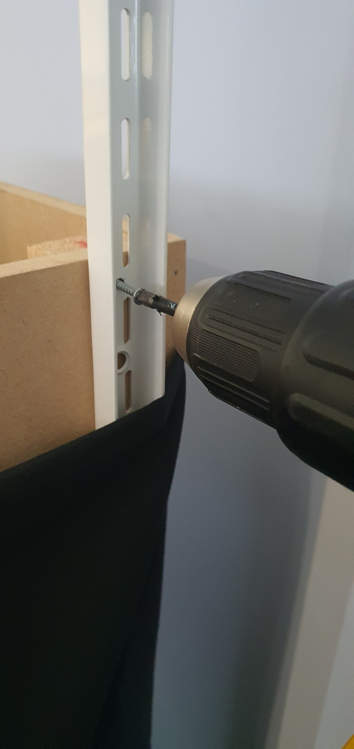
I levelled up the base of the upright with the base of the module and marked the hole for the upper screw. being sure to ensure that the screw would be going into the cross support of the module and not hitting any of the brad nails used during the modules construction.
Then I used 3.5mm x 30mm screws to secure the upright.
Using the top of the module I squared the upright to be vertical and then ran in a 5x60mm decking screw (mainly because i had them on hand) into the lower hole securing everything square. These are probably over kill but this should prevent the uprights from moving when under load.
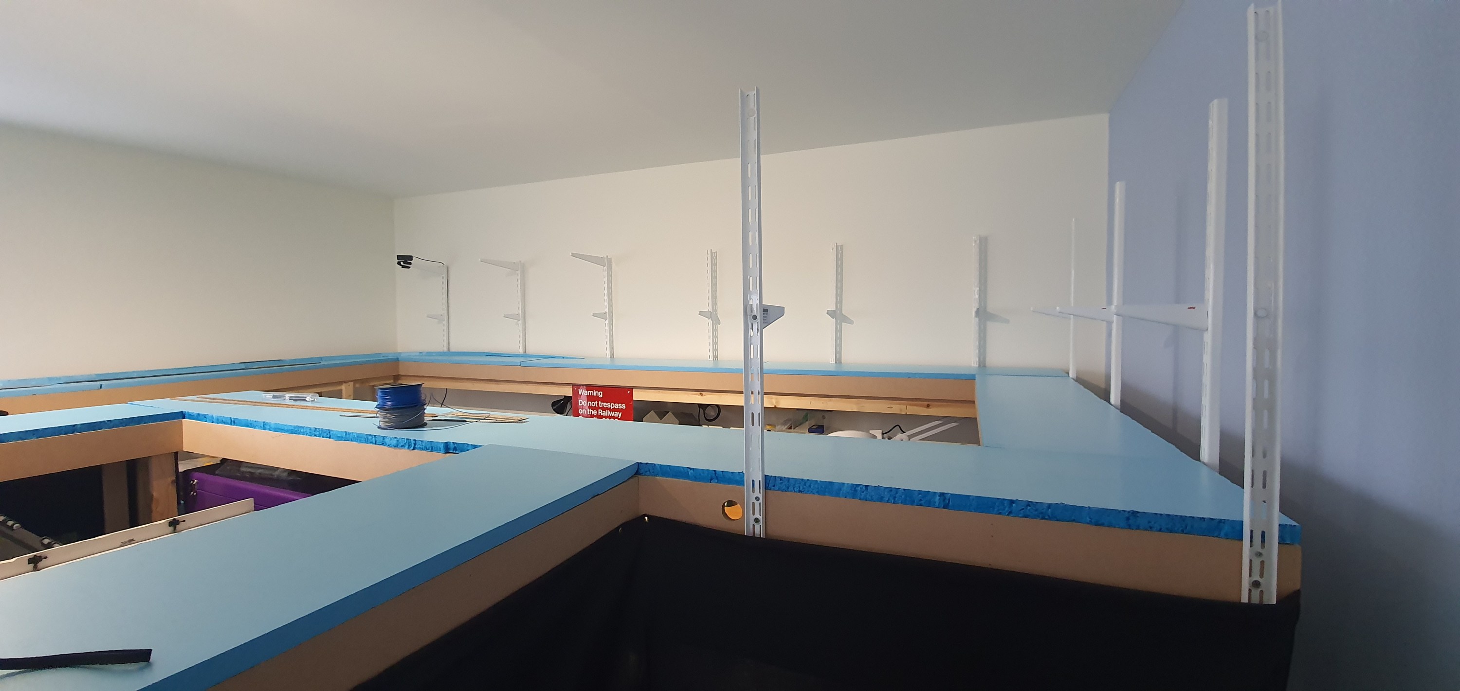
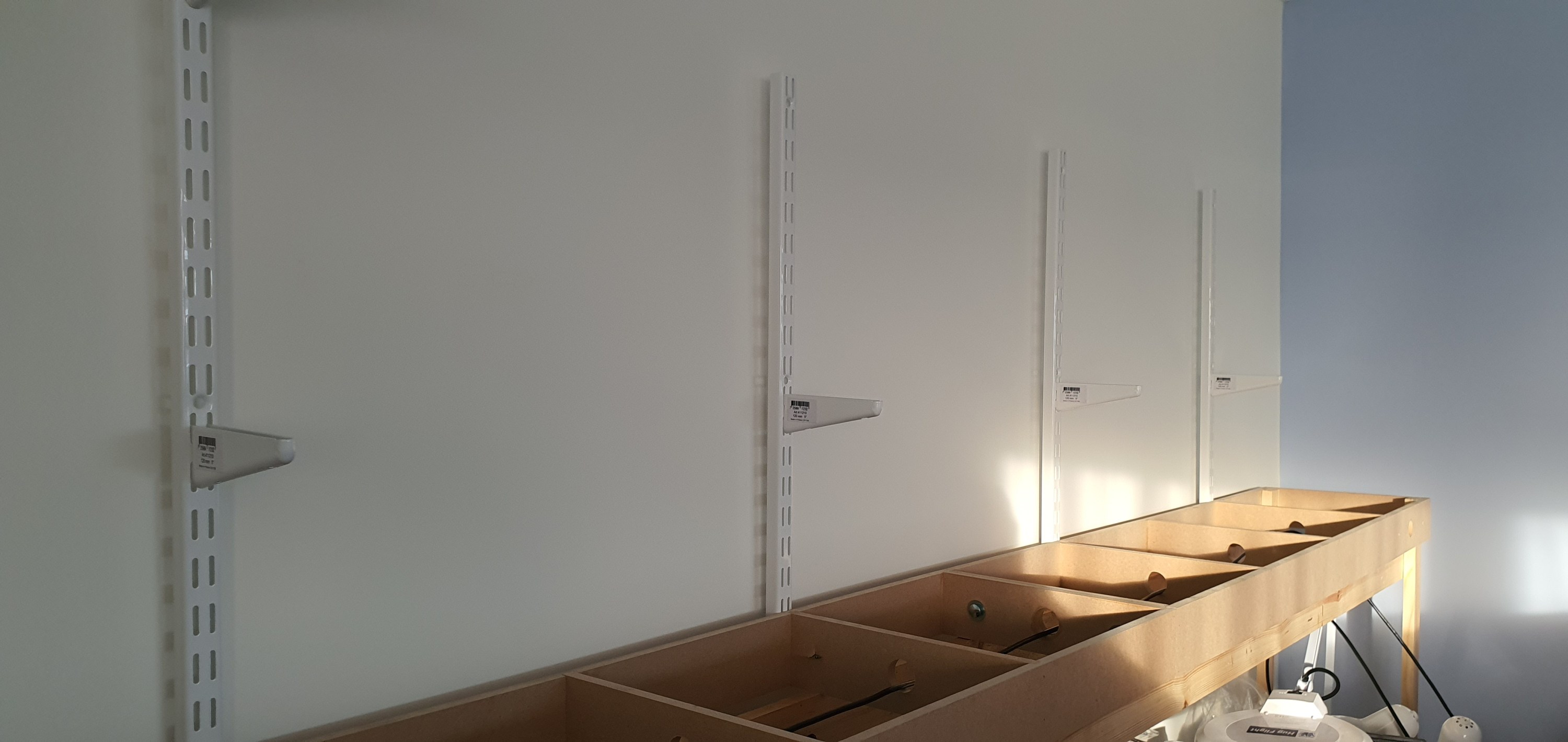
Here you can see what the uprights look like in place on the module I removed to allow the large rear section to swing away from the wall. it certainly was alot easier to do this module than the others.
Here you can see the completed view of all 11 uprights in position. There are above my workshop area and over the coming weeks I’ll be adding the back sceneswhich will permantently take away my ability to take these overall shots.
In these two shots taken whilst the modules were detached you can see the brackets for the second deck and eventually the lighting rig. The second deck supports are 120mm long which will enable a small shadow box effect above the lower deck. The upper supports are 320mm and will extend just in front of the lower module deck supporting lighting for both decks and completing the shadow box look.
Look out for tomorrows post where we will look at scenery planning on the Ackerville section of deck one.
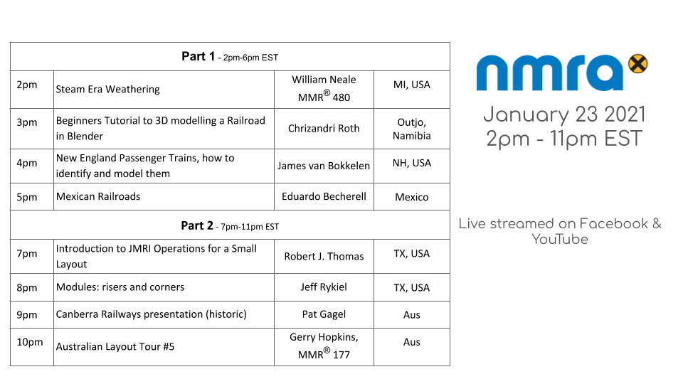
Well its not everyday that we get a new podcast especially from an NMRA division but the Twin Cities guys and girls have done it. The division is based in MSP or the Twin Cities to those in the 🇺🇲.
The effort led by Thomas Gasior MMR released its first episode on Friday Jan 22 2021. The first episode talks about using car cards and waybills for model railroad operations helping your cars move with purpose on your model railroad.
I have a friend Jordan in Ohio who is always planning new freemo modules or layouts and on Monday he asked me to help him with his track plan for a basement layout.
A quick run down of his requirements were:
Must haves:
set circa 1920
10-12 car trains
Has to be modular no longer than 5ft modules
needs to go against a wall but access at each end is required.
Nice to haves:
Urban scene
Must be able to pass two trains
Classification Yard
Some Industries to include LCL
Roundhouse/loco servicing
2/3 crews but could be operated by one person.
House track in front of the Depot (its 1920’s they ran Passenger Cars)
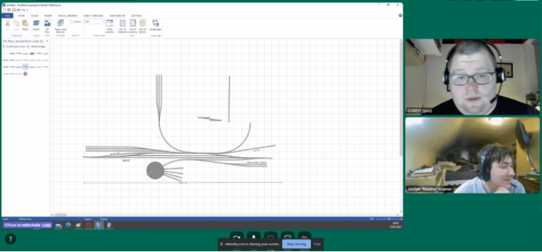
I love drawing track plans and layout design and I often help folks out with their plans. With Jordan being in Ohio and myself in the UK we used some video conferencing software and shared my AnyRail screen so we could discuss the plan together as we went. To be honest he watch a youtube video on Dave Abeles Onganda Cutoff but hey thats how it goes.
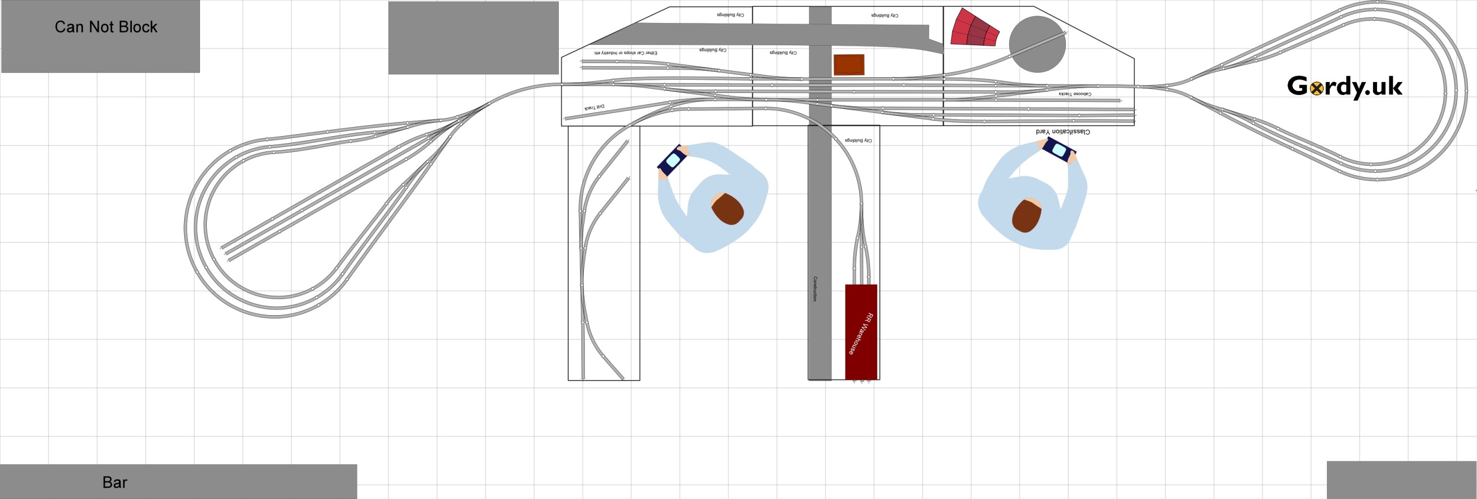
What we eventually came up with was a small yard buried in the inner city jungle of 1920’s Ohio which tall buildings forming urban canyons and view blocks. The yard has a 19 car capacity and two pennisulars provide local switching work for the yard, including a LCL Railroad Warehouse.
On the otherside of the yard is a small roundhouse and space for either a car repair shops or an REA or other warehouse in the urban part of the layout. The layout can either be operated with staging yards or part of a Freemo set up or even on its own as a small switching layout.
100mm Grid all turnouts Peco #8 and two curved #7
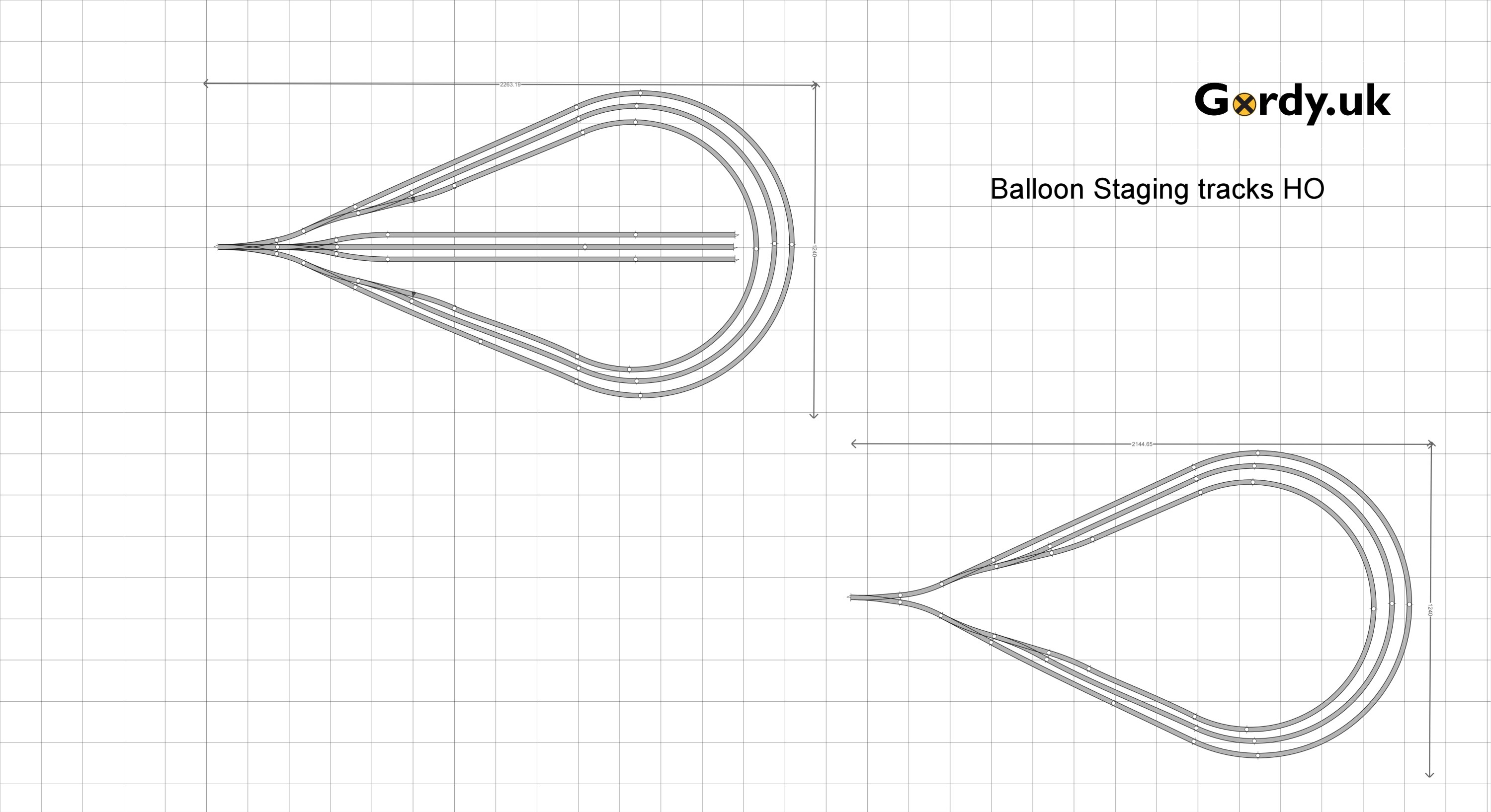
So now we need some staging, I suggested to Jordan that two Balloon style reversing loops one with stub ended staging in the middle would work best for him as they can be made using 4×8 sheets of ply.
Ah ha! We are making progress so lets see this thing finally fitted into the space that Jordan has. Of course it does and its obvious this is going to be a really fun layout to run. The grey areas are places that can’t be covered or blocked but we have avoided those and there is still plenty of space in the room for entertaining.
Well its the start of another weekend so lets get back to the workbench.
This is a short follow on from my post on Tuesday and this will just cover the same principles but focussing on using flex track for your helix.
Start by selecting the type of flex track you want to use. In this example peco code 55 but the principle is pretty much the same with any type of flex or scale.
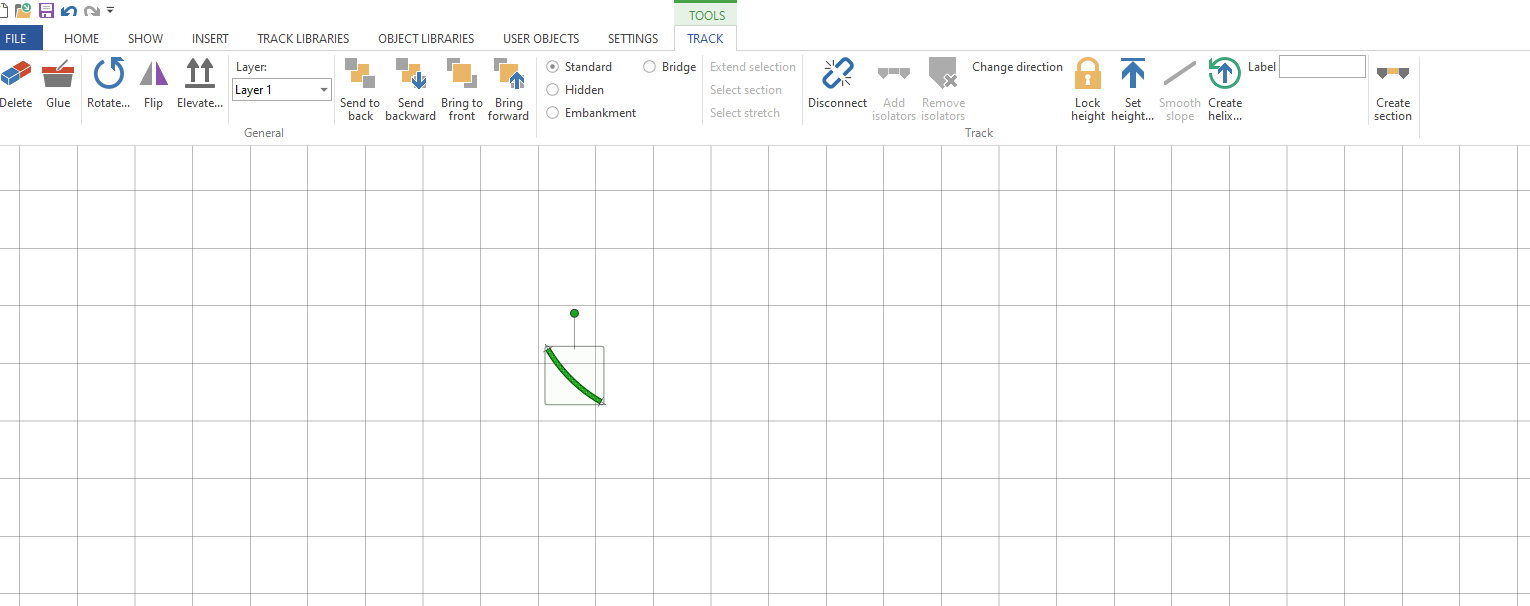
Once you have your flex track select it and then click on Curve flex … on the tool bar. The ‘Set flex curve wizard’ will pop up in N scale you can enter 90 as the angle (the max is 90) but in other larger scales you may need to use a smaller angle, maybe 45 degrees. Then enter the radius, I am goint to use 457mm or 18″ in this example.
Once you have a curve you can then open the helix wizard as we did previously, make sure the track is still selected.
Enter your start and end heights, in this example 225mm (approx 9″)
As you can see I have saved time here and adjusted the turns to 3.5 which would have a slope % of 2.2% its not ideal but most N scale locomtives will run quite happily up that grade with a train. With a 914mm or 3′ radius which is going to result in a helix about 6’6″ wide you would only have a 1.1% grade. Most of us wouldn’t be able to give up over 40 sqft in our train room for this monster Helix although in HO thats quite common.
Anyway back to the helix click ok and you will have your helix on your plan. to quickly see how much track is swollowed up by the helix double click on it and you will see at the bottom of the screen the track length. here its 10,051.25mm which is over 10m(33′) of flex track in a small 3.5 turn helix.
I hope this helps you add your perfect helix to your layout. The Waukesha Sub & WSOR Northern Sub N Scale layouts I am constructing will have 4 helicies (yes thats the plural of Helix) on the layout.
I now have stickers available from the GordyUK store, those in the US can even get Die Cut versions. These look awesome on your facia, toolbox or workbench.
Using software to draw your layout is becoming much more common than paper. Most like AnyRail will even tell you the quantity of materials you need to build your layout and can draw your layout in 3D.
However one of the things people often ask me how to do is draw a Helix so here we’ll cover a few short steps to have you drawing a helix using set-track or Kato Unitrack pieces.
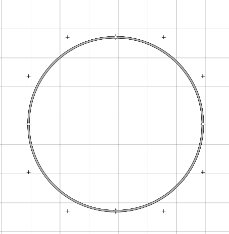
First select the radius of curve you desire and drop it onto the work area, for this example we are using curved radius 381mm (13.75″) x 30 degree pieces so we will need 12 per circle.
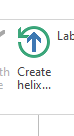
Once you have done that select the Create Helix option in the tool bar.
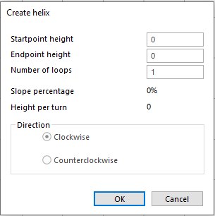
The helix wizard will open
If you have set the height of your layout then enter that as the start point height.If you haven’t then set to 0 if you enter a height thats different to the height of the track you are trying to connect to then AnyRail will prevent you connecting those sections of rail. Imagine its like having one piece of rail on a table and the other on the floor looking down it may appear you can connect them but there is vertical seperation. As we are now adding a Helix to our layout we need to remember to think in 3 dimensions.
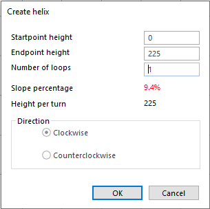
The next thing to do is enter the end point height, this will be in the same unit of measure as set for the rest of your project so if working in mm enter the value as 349.5(mm) not 13.5(inches) otherwise you’ll get some interesting slope % results. My layout is 225mm between decks so we’ll go ahead and enter 225 into the endpoint height.
As you can see the software has auto calculated the slope percentage and height per turn. I haven’t changed the number of turns so its off the scale and unlikely that any loco will pull anything up it. So next enter your turns, if you don’t know how many turns you need then enter the minimum clearence you need between decks in your choosen scale in this case its 65mm for N Scale to make sure you can get in and re-rail any cars. Remember to include the thickness of the helix material, track & roadbed in this calculation.
Divide the height per turn you want by the difference in height between the start and end points. Note you need to keep in the same unit of measure for clearance and heights so do a conversion if necessary always remember its 25.4mm to 1 inch.
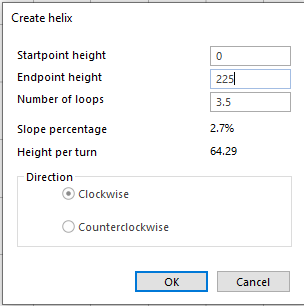
In reality we are not going to be that precise with a helix so round up or down to the quarter turn, we’ll use 3.5 turns for this helix.
So now we have a 2.7% slope helix if this is too steep for you then you have three options open to you, either increase the radius if space allows or reduce the clearance height you are happy to accept or make an oval shaped helix to add run to each turn. Its most likely that you will have to increase the radius or go for an oval helix.
For example using a huge 481mm (18.91″) radius part with the same settings gives you a slope percentage of 2.1% which is probably more appealing than nearly 3%
The last thing to do is decide if you want your Helix to run clockwise or anti clockwise, select what works best for you and hit ok. AnyRail will then build your helix for you.
Types of Helix
Its not just the slope % you need to consider in the design of your helix you also need to make sure the exit and entrance are where you want them to be on your layout. A 1 turn helix will have your train exit in the same direction it entered if there is a wall in the way thats probably not desirable. So I produced this handy Helix guide for you to use.
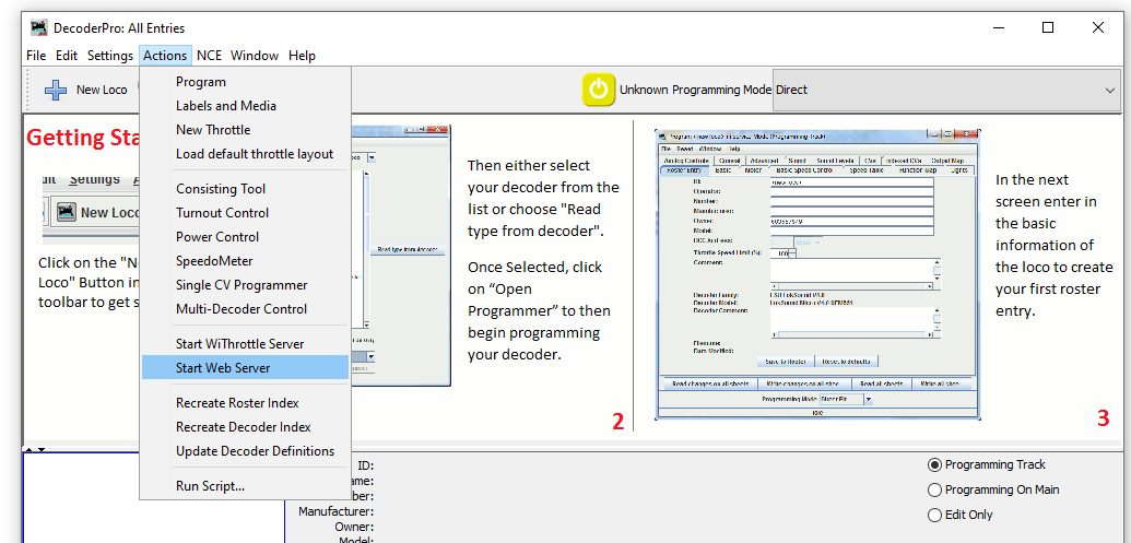
With the layout now connected to the computer we can set up a JMRI Web Server to use Wifi throttles such as a smart phone or even allow remote operations through the web.
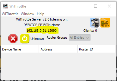
To start a web server with JMRI open and connected to the NCE system navigate to Actions>Start Wi Throttle Server
You’ll see this window note down the IP Address and port number (highlighted in yellow). In this example the IP address is 192.168.0.31 and the port is 12090. This IP address is internal to your home network, don’t panic your router firewall will prevent access to anyone from outside your home gaining access to your layout.
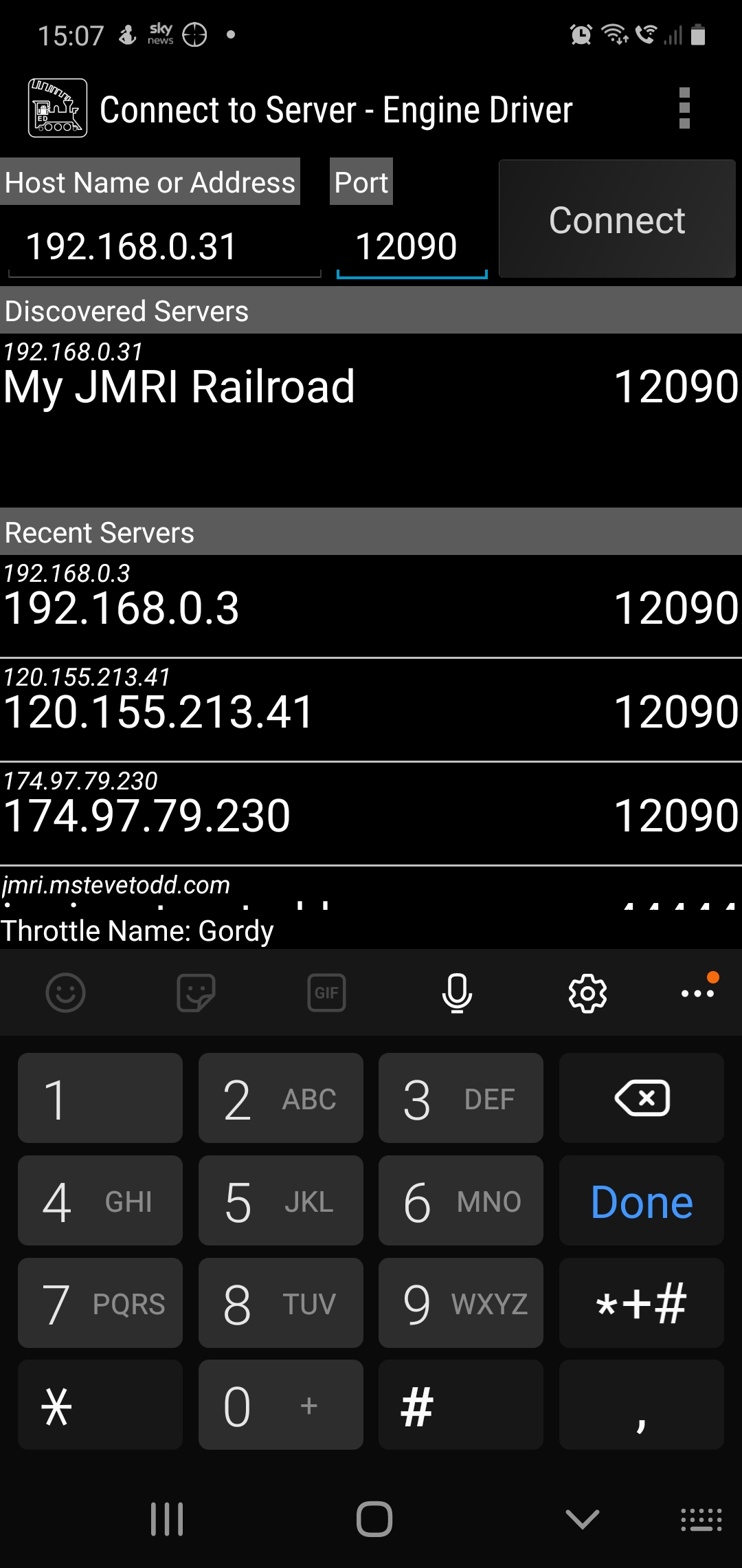
Now JMRI is running and allowing any device with WiThrottle or Engine Driver or any other supported app to connect to your computer and through it the layout. So lets in this example use the Android app Engine Driver.
When opening the app your device will either have found the server or you can enter the IP address and port number at the top as shown above. Hit connect and then you should be able to aquire a locomotive on your layout. If you have entered your roster into JMRI then you can see all locomotives in your roster rather than entering the DCC address.
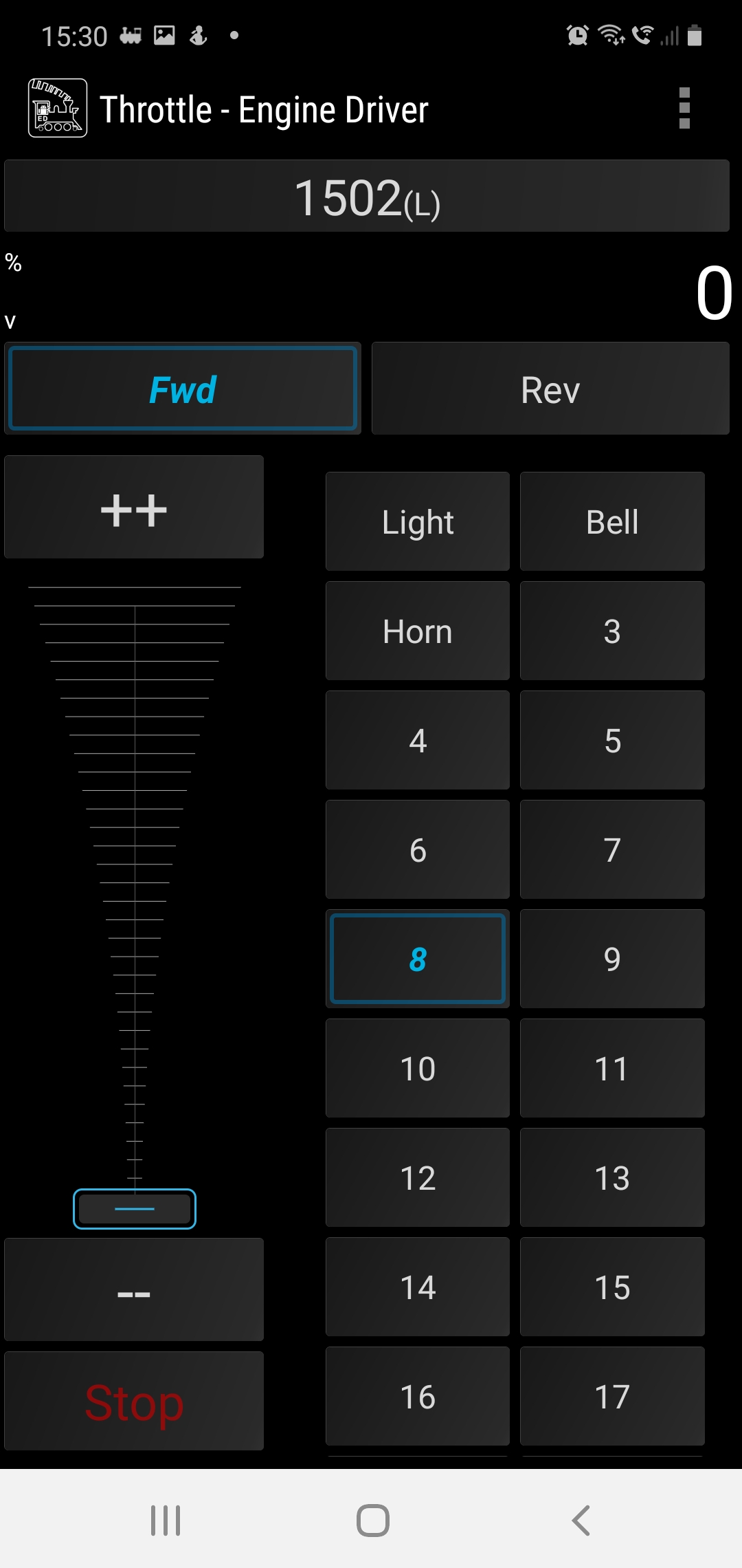
Engine Driver Throttle in Dark Mode, the loco is selected using its DCC address 1502
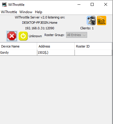
Back over on the PC we can see how many wifi throttles we have connected on the WiThrottle screen.
This is a great way to add more throttles to your layout and to the basic NCE PowerCab system which limits you to only having 4 cabs.
I hope youhave found this useful, its not a huge step from here to remote ops so we’ll cover that in a future post.
For now, stay safe and keep working on your railroads.
This was supposed to be a nice easy post on a Friday evening followed by a beer or ten. However as with most things electronic its not gone quite to plan.
So what are we attempting to do? well in order to have the layout run from anywhere in the world it needs to talk to the computer and the plan is to do that using JMRI and a USB interface. Its usually simple and I have done this on my other layout before with no issue. Not today it would seem but anyway lets talk about the process.
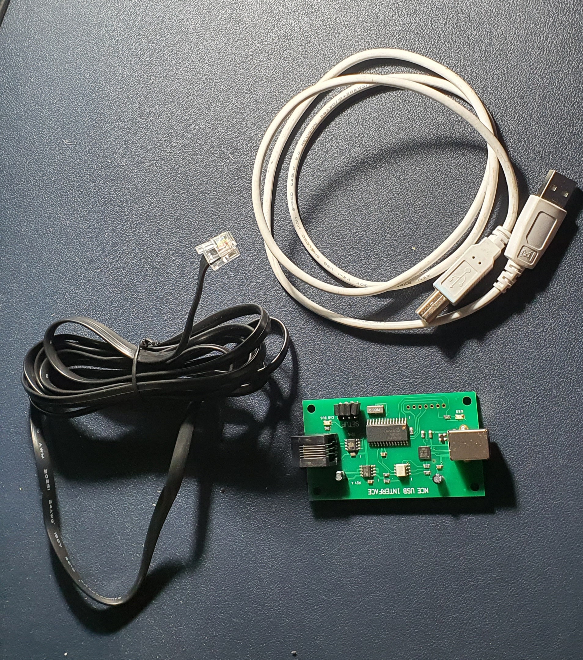
So this is what you need to interface an NCE powerCab to your PC. Its a standard NCE Cab bus cable, a NCE USB Interface and a USB A>B cable like you use for hooking up a printer.
To set up power up the Powercab and then plug the NCE USB Interface into the spare Cab socket and you should be able to detect the device when you plug it into your PC.
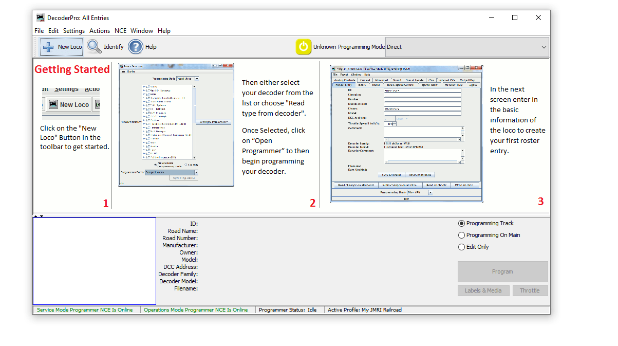
When you open JMRI you will be asked to set up connections if not go to Edit>Preferences and you’ll see connections at the top
Select NCE as the Manufacturer and NCE USB as the system connection. Its really important you select the correct COM port, if you don’t know which one to use then go to Device Manager on your PC (if windows) and find the ‘CP210x USB to UART Bridge’ thats the NCE USB device look for the com port and make sure this matches in JMRI. Save your settings and exit.
When you return to the Decoder Pro screen you should then see the two green indications at the bottom of the window. If like mine did for the best part of an hour these go red and are not connected after a few seconds but are green to start with go to JMRI downloads and update the version on your PC. Then un plug and start everything again. If its red and never green check you have selected the correct COM port.
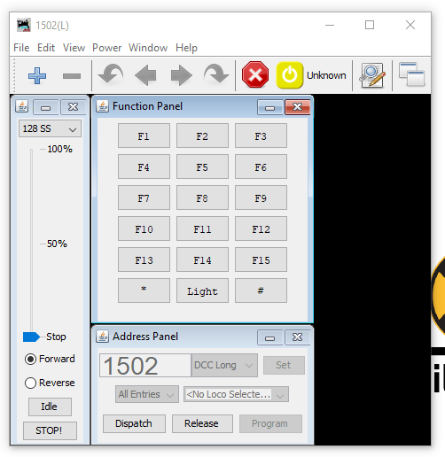
Then to test you have control of the layout go to Actions>New Throttle you’ll get this window
JMRI Throtle Window
Select a loco on your roster thats on the layout by entering the address in the Address Panel and click on set. This will aquire the locomotive. Then see if you can use any of the functions if a sound loco Horn is always a good one to test. If thats all working then you are set up and ready to go. You can either go to the next stage and use Wifi throttles or even allow remote ops or program your locomotives..
We’ll cover the JMRI Web Server for WIFI throttles and also Remote Ops in a future blog post.