For the past 6 weeks I have been working with the team from the Rocky Mountain Train show to put on a virtual event. This was live streamed yesterday here is the link to the Youtube quality version of the livestream that you can watch on your home TV or your computer. There are presentations form manufacturers, clubs, museums & layout tours from the Denver area.
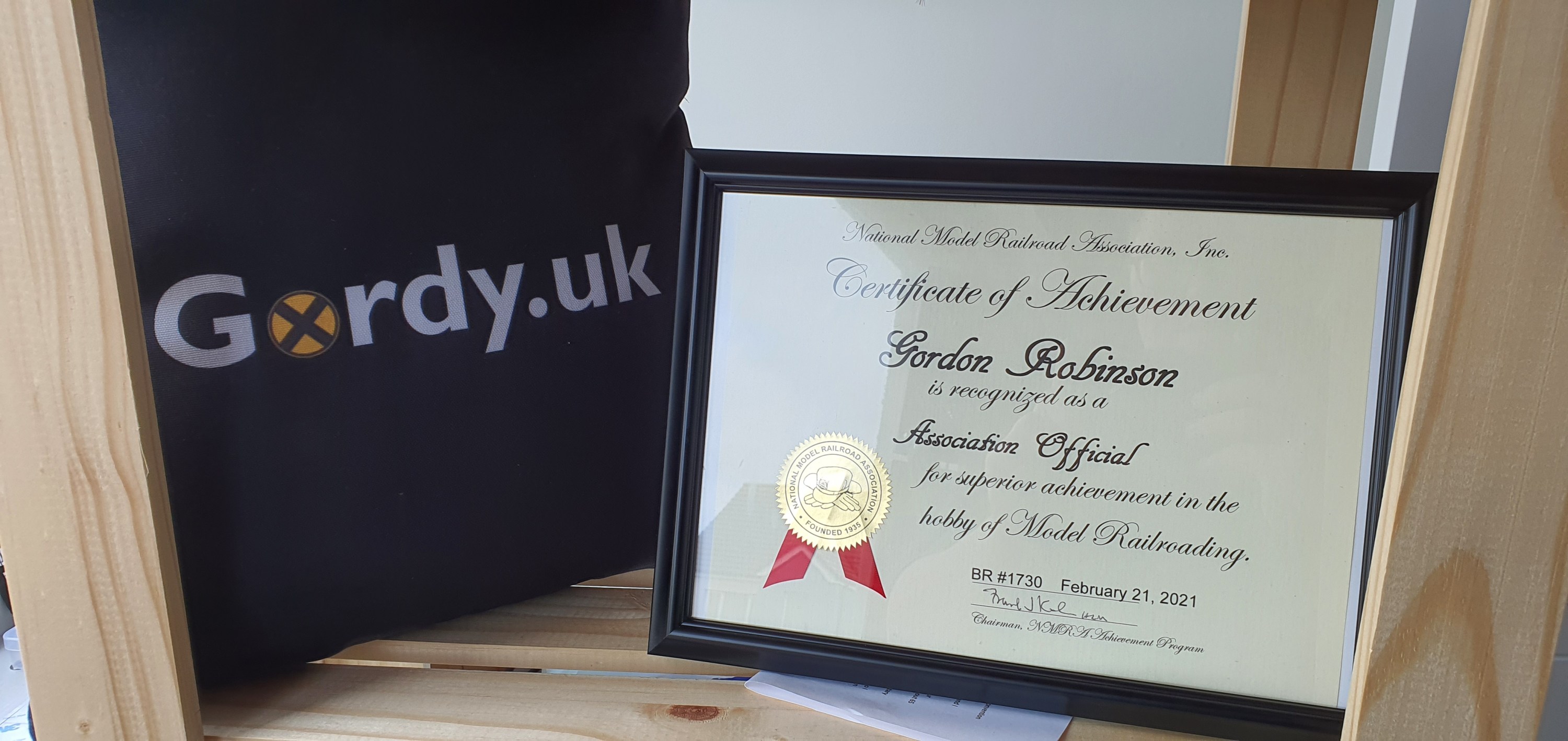
I have reviewed my Association Official AP Cery from the National Model Railroad Association, this was for my work as Divison Superintendent for the Scotland Divison of the NMRA British Region.
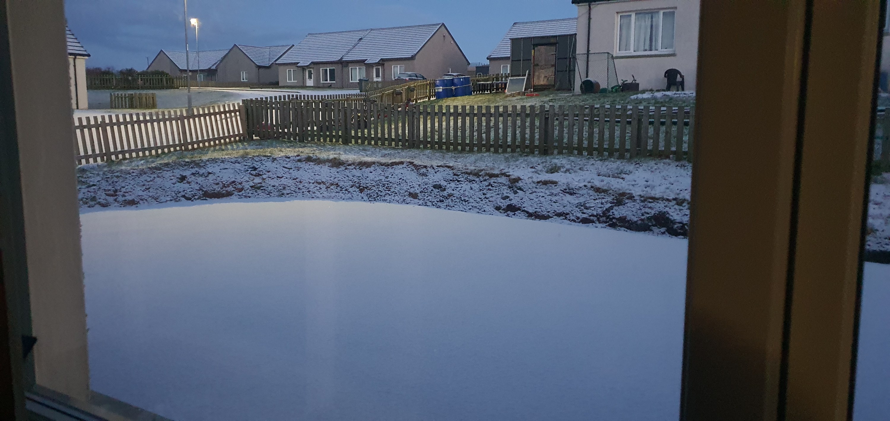
Just a quick post to say thank you to a fellow model railroader for sending more snow to Orkney. I don’t know what the Orkney drug dog thought of this package.
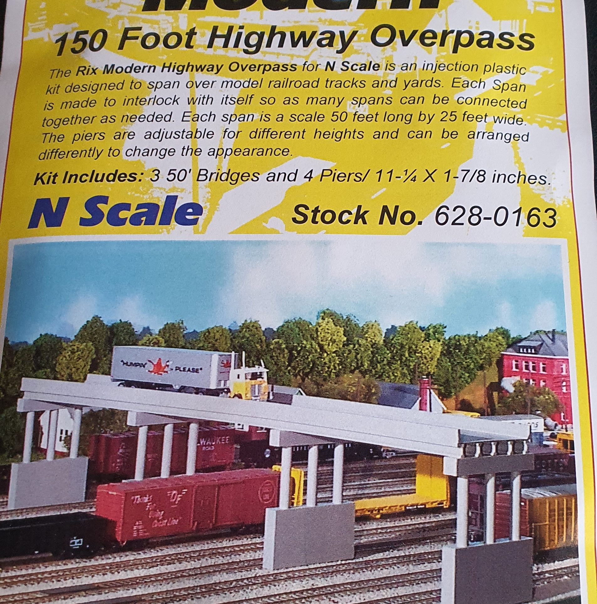
At the south end of Ackerville there is a highway overpass that crosses all the tracks. To model this overpass I used a Rix Products modern highway overpass kit. It is narrower than the prototype but the whole Ackerville area is compressed by 25-50% so having a narrower bridge still fits in the scene.
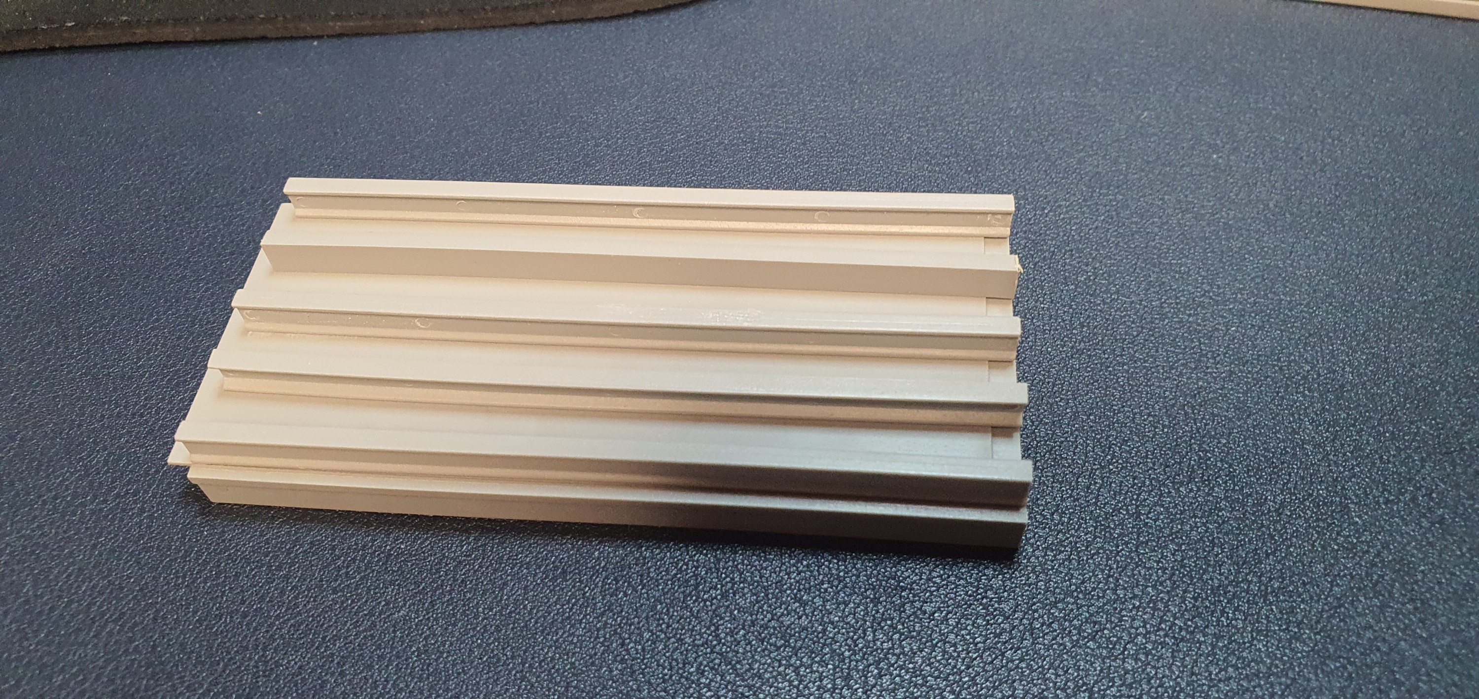
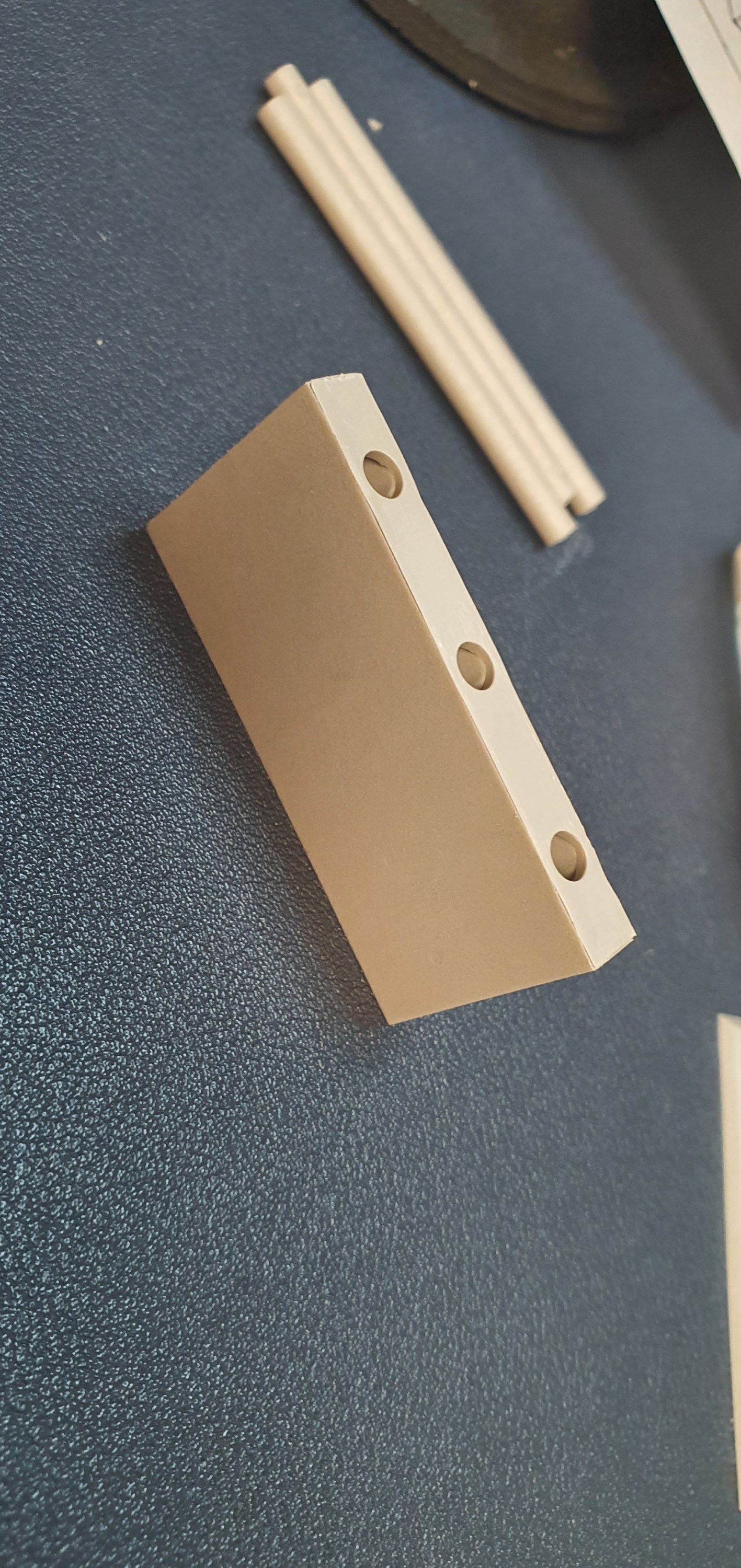
Lets have a look at what is in the packet.
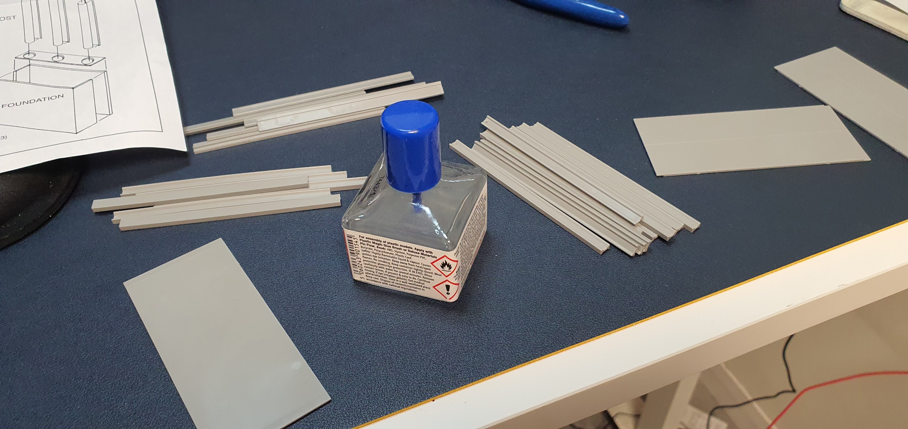
The first thing to do with the kit is to cut and file the girders from the sprues and seperate them. Here you see the I beams, C beams and barriers. The bridge decks each have three I beamsn and two C beams under each 50ft section.
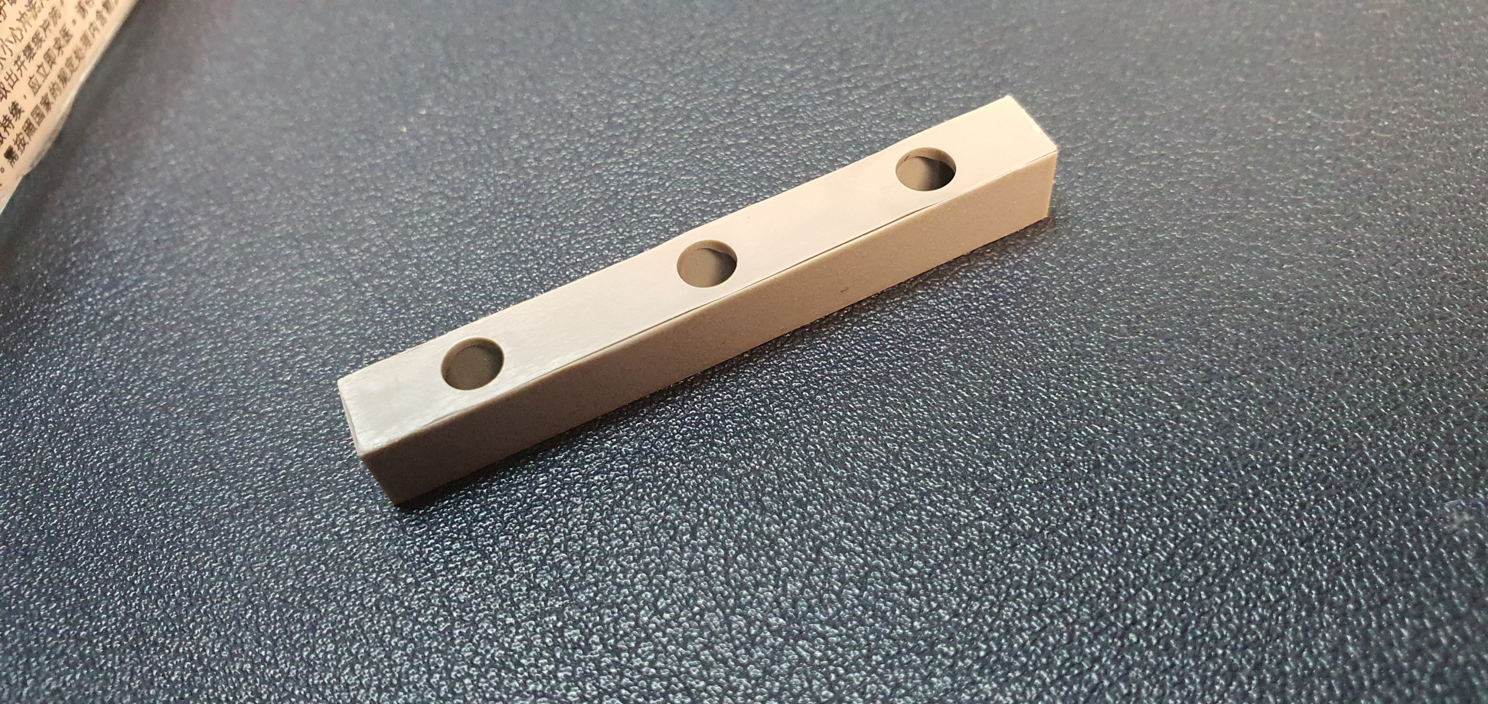
The I beams go in first and then the C beams between each I beam.
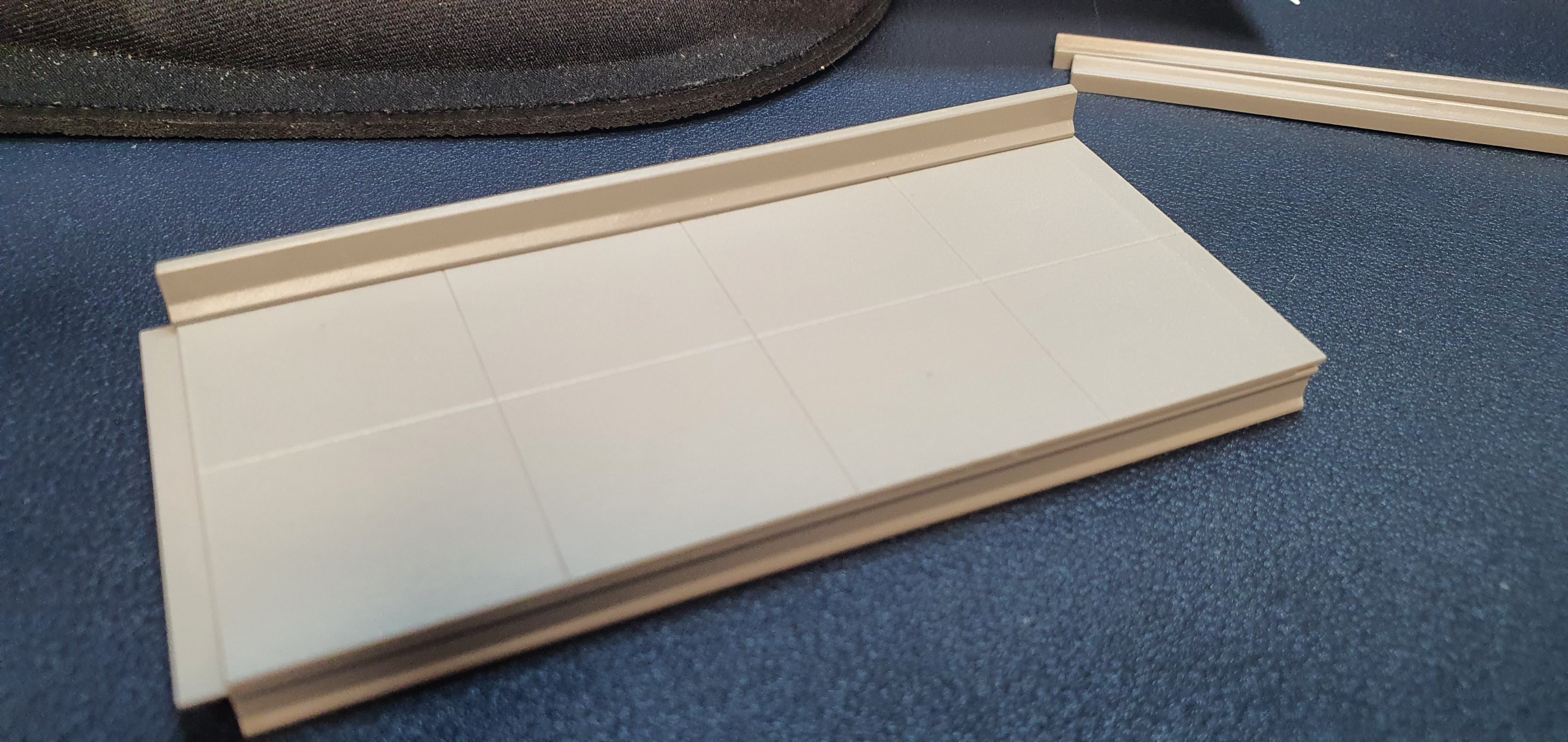
If the bridge is being assembled in one piece then I would suggest that you glue the road deck sections together on a flat surface and then line the beams up on each section.
Then I added the crash barriers to the edge of the roadway.
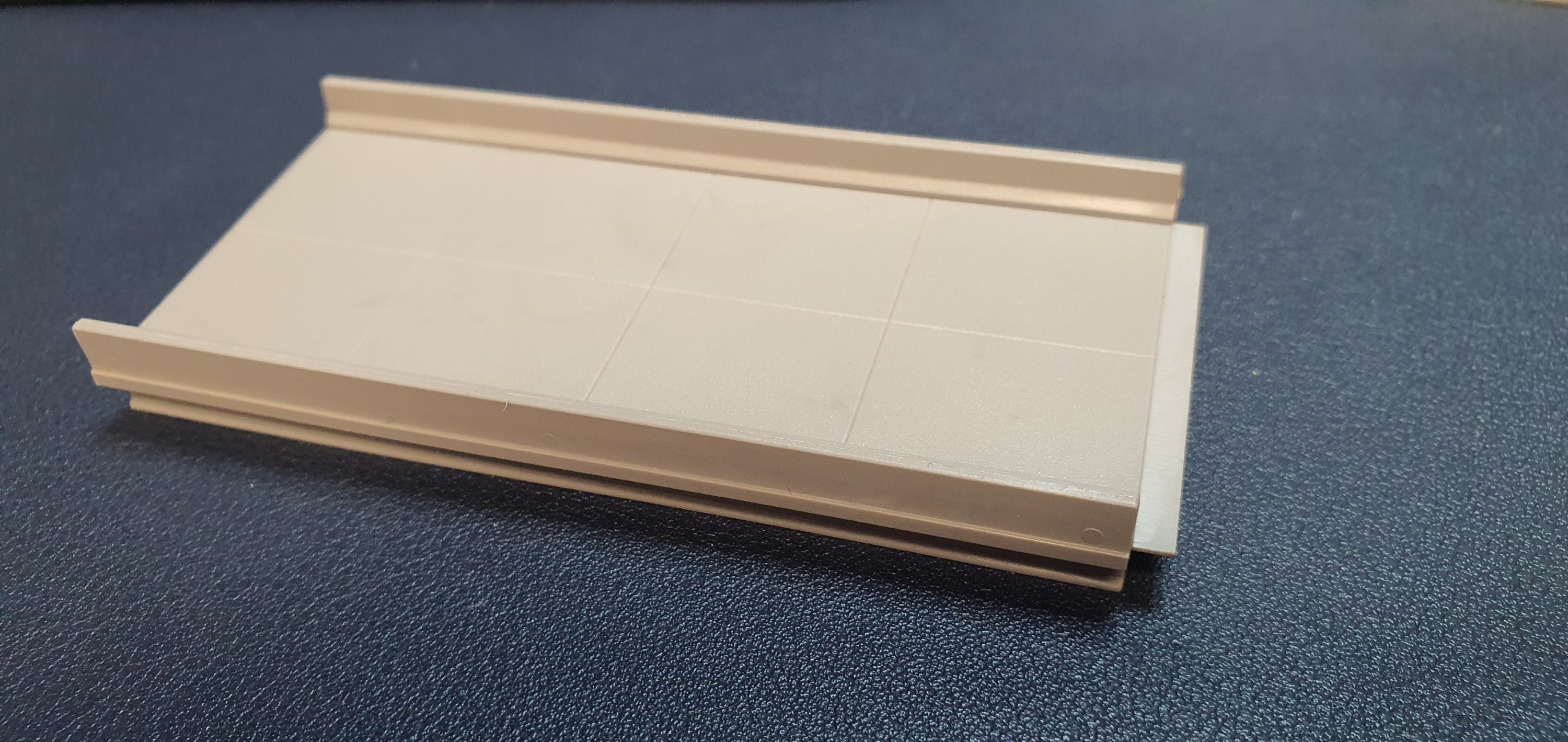
Here is a completed 50′ bridge section
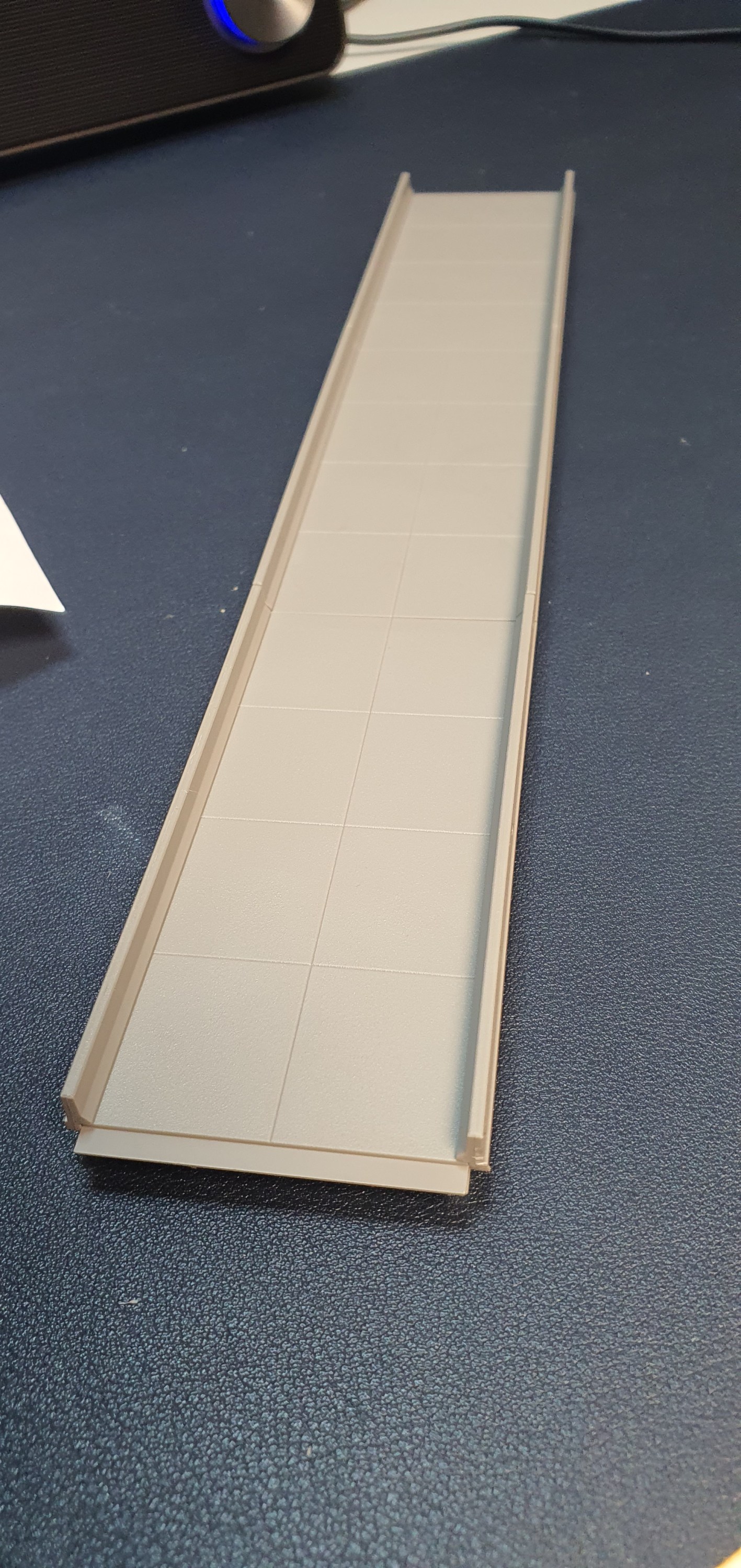
The completed 150′ of bridge deck. So time for the piers.
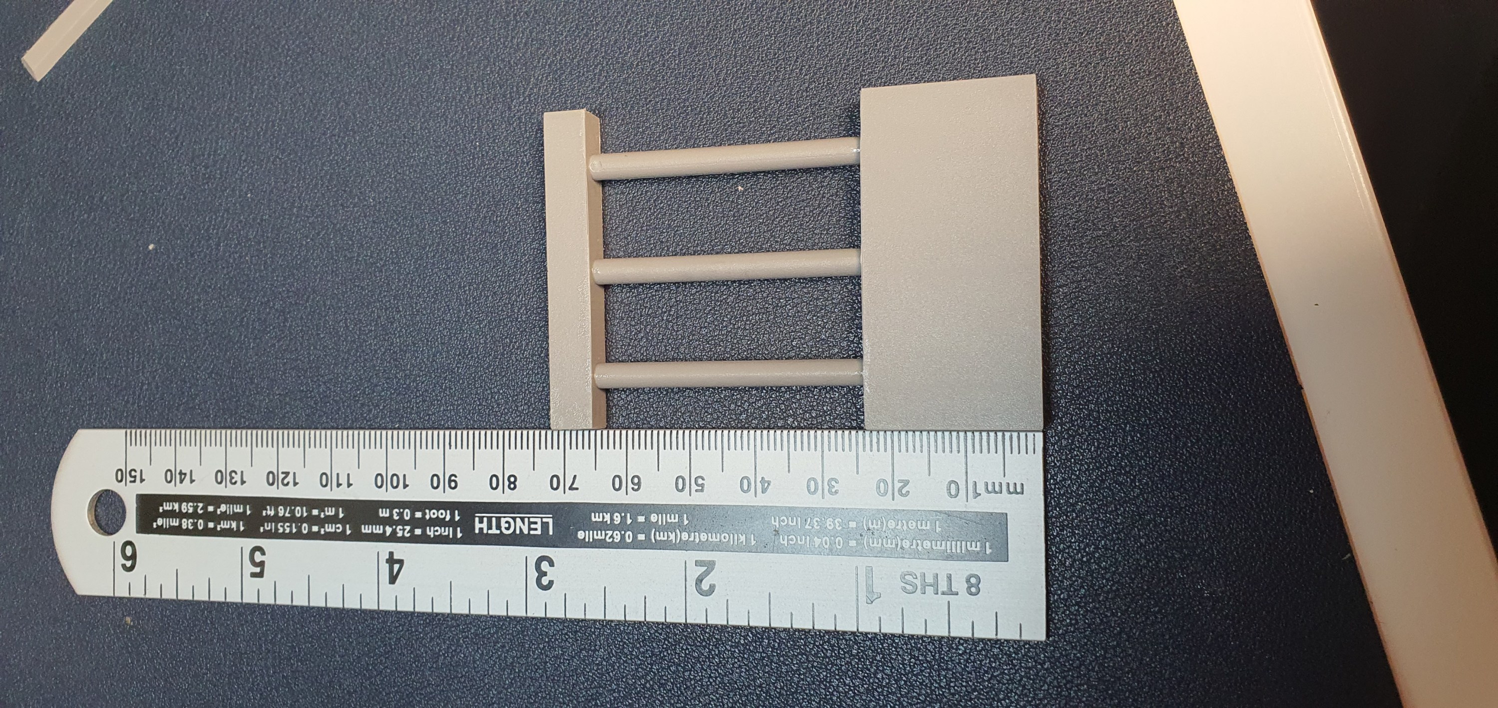
Start by assembling the upper and lower sections of each pier and then measure the hight you need the bridge to be. Now on this section of Ackerville the WSOR is 20mm higher than the CN mainline so I want my bridge to be 70mm above the CN mainline.
Once I was happy with the hight of the piers I glued the posts into place.
Done, but lets get it on the layout and test everything before we take it to the paint booth in part two.
This looks awesome, well yeah I am biased and I know its nothing like the actual bridge in Ackerville but no one in Orkney will have seen the real bridge. By making the deck solid I am able to offset the piers to allow for a larger gap between the piers on the WSOR section and narrower for the CN.
Ok I see the middle pier is too low but we’ll get that fixed before final installation. right I don’t know when part two of this builld will be getting some paint and weathering on it and we’ll get it installed.
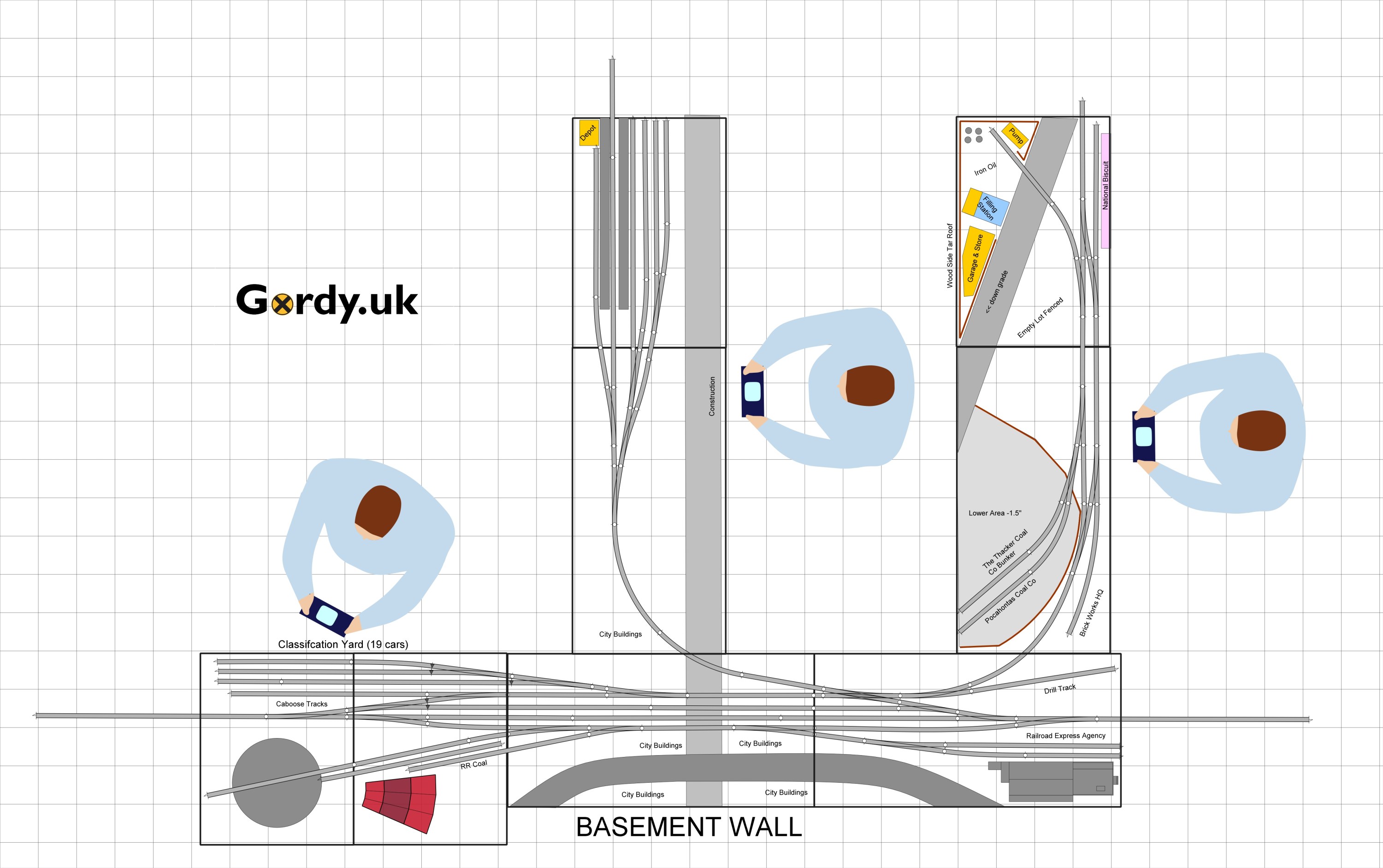
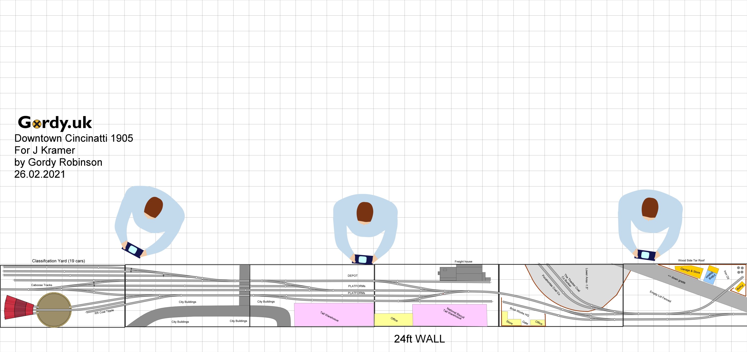
Well Jordan came to me and said hey how would my plan look in a 24ft x 2ft space? Theres only one way to find out eh!
This was where we got to last time in a 12ft x 12 ft space. When changing space its important to re-inspect the givens list so we checked in with Jordan.
He wanted the following
layout fed by two helices for continous running and staging underneath
Keep the yard area & round house
Station area for communter trains
Keep City feel
Try not to change the switching area on the right hand pennisula
So my first stab at chaging this I kept the yard and rotated the pennisula. the additional module in the middle is where I added the station area with platforms. Jordan approves but we can always make improvements.
Can you spot the changes??? Well yeah lets talk them through, so national biscuit has moved to one of the large warehouses behind the depot. That gives you a larger run around to serve the coal yards and brick yard. I have also added a passing siding to allow trains to avoid the yard and depot area.
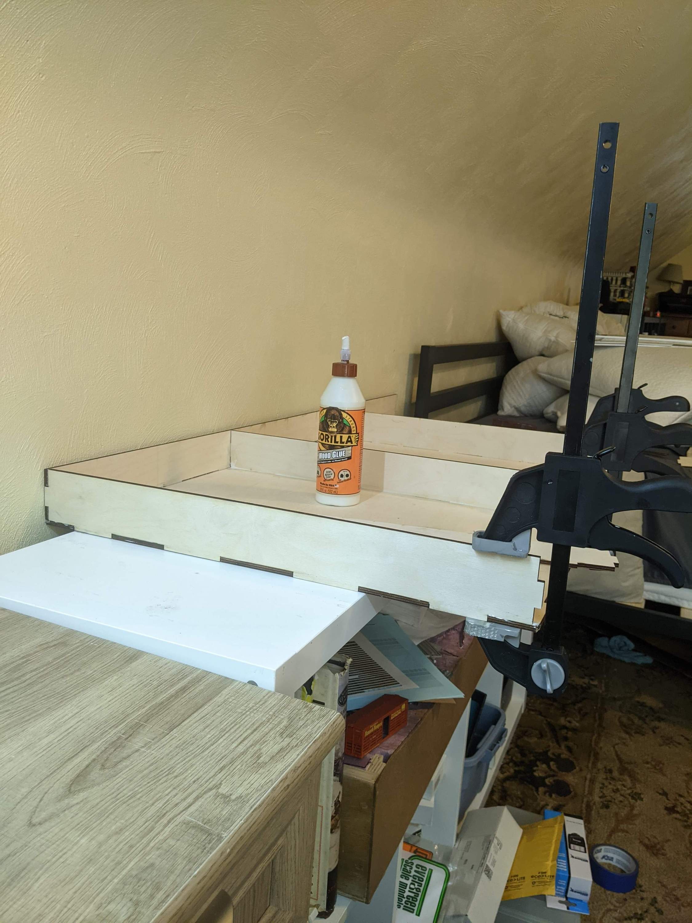
Each of these modules are 4ft long and Jordan plans to follow the TOMA aproach building two modules at a time. The first two modules have arrrived and Jordan has shared this picture with me of his modules from CMR products.
Well thats it for today, the postie brought a helix and some other parts today so we can get on with some work on my own layout tomorrow.
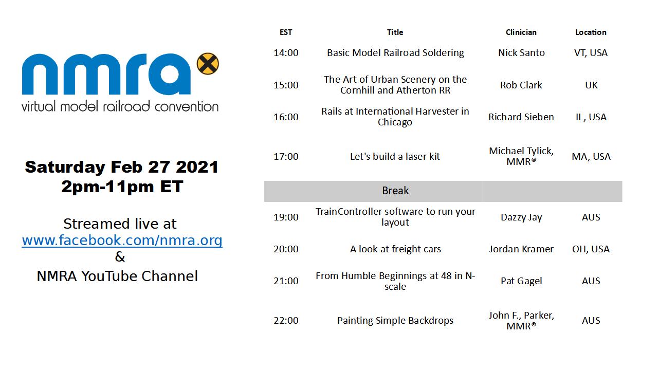
Well its our Monthy NMRAx event today so this is a wee reminder post rather than a modelling post but don’t worry i did do some modelling last night mostly re-drawing a track plan for one Mr Kramer to fit in a longer but narrower area.
Anyway today its NMRAx for those in the USA its from 2pm EST until 11pm EST with 8 hours of clinics with a one hour break.
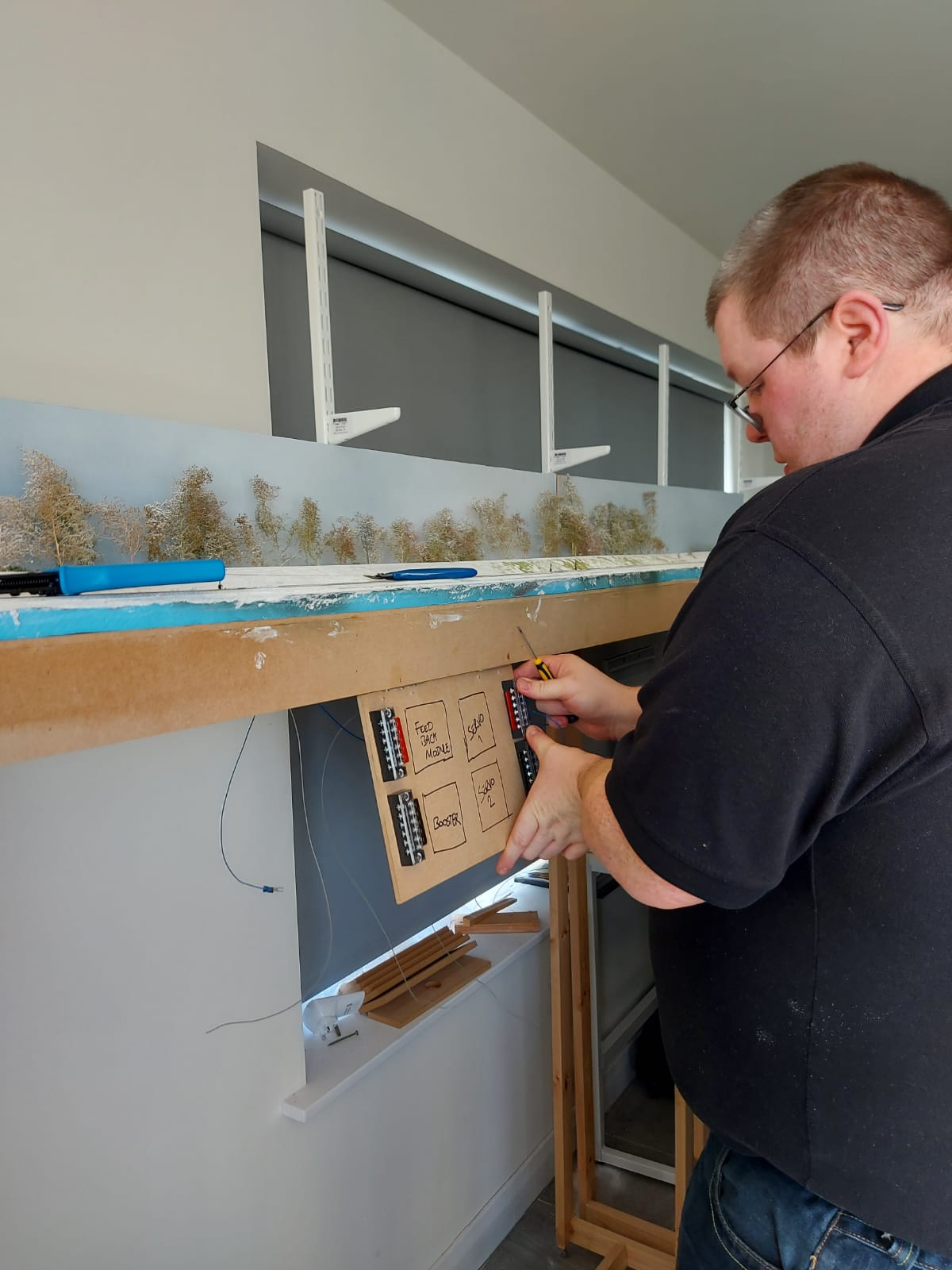
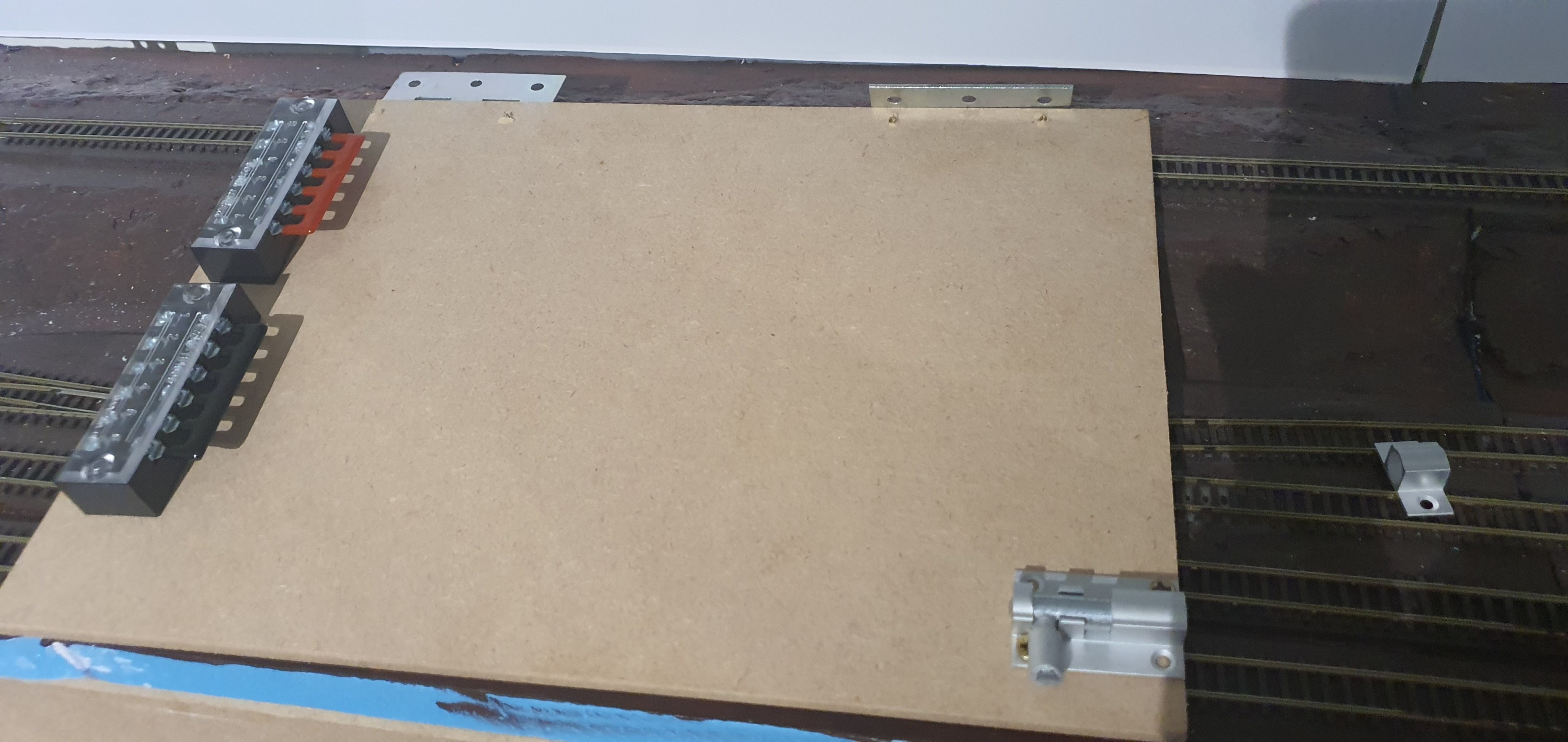
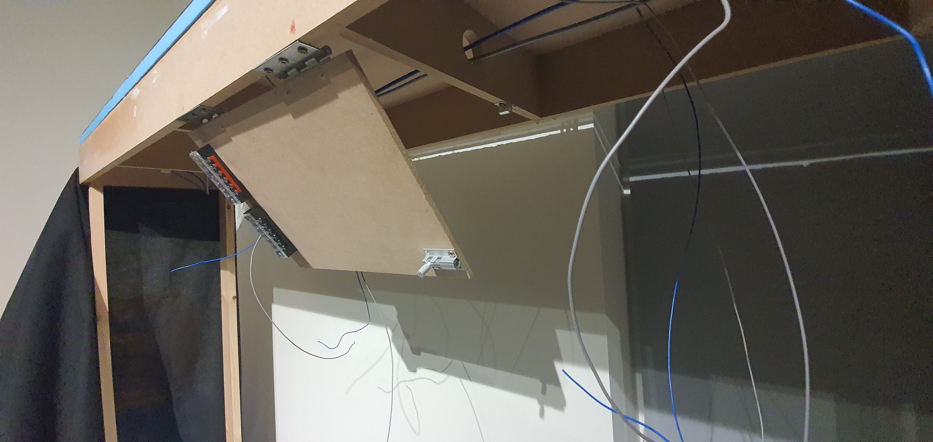
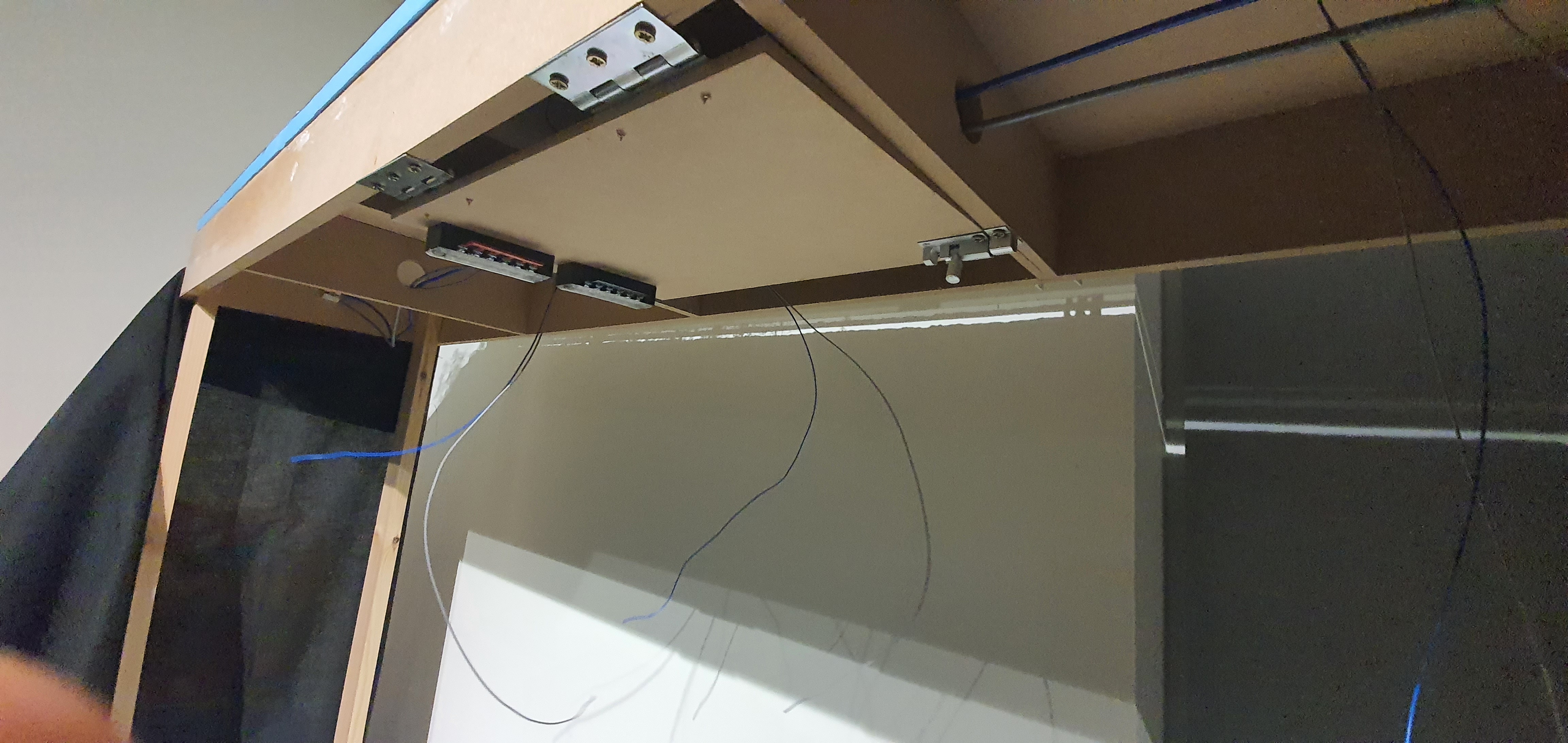
Ok yeah you have seen this concept before on another module but as we move to wiring up ackerville I wanted to get the board in place for the module we are now at scenery stage with.
This is just an A4 size 6mm MDF board with two hinges and a 38mm bolt
As you can see the boards are simple but have screw terminals for the feed wires so the wiring on the board to the electrical modules can be neat and tidy.
The hinges are screwed to the underside of the module frame and the board will swing down when I need to work on it and up under the layout when in normal use. There should be minimal climbing under baseboards.
I dont have all the modules yet because I don’t need them. I’ll get them when I do so for now the screw terminals will be shorted so all track feeds get power. I’ll remove them when I get the modules installed.
Here is the board swung down and you can see the locations for the electrical modules. These won’t go on yet, I’ll only install them when I have enough track down to warrant a operating session.
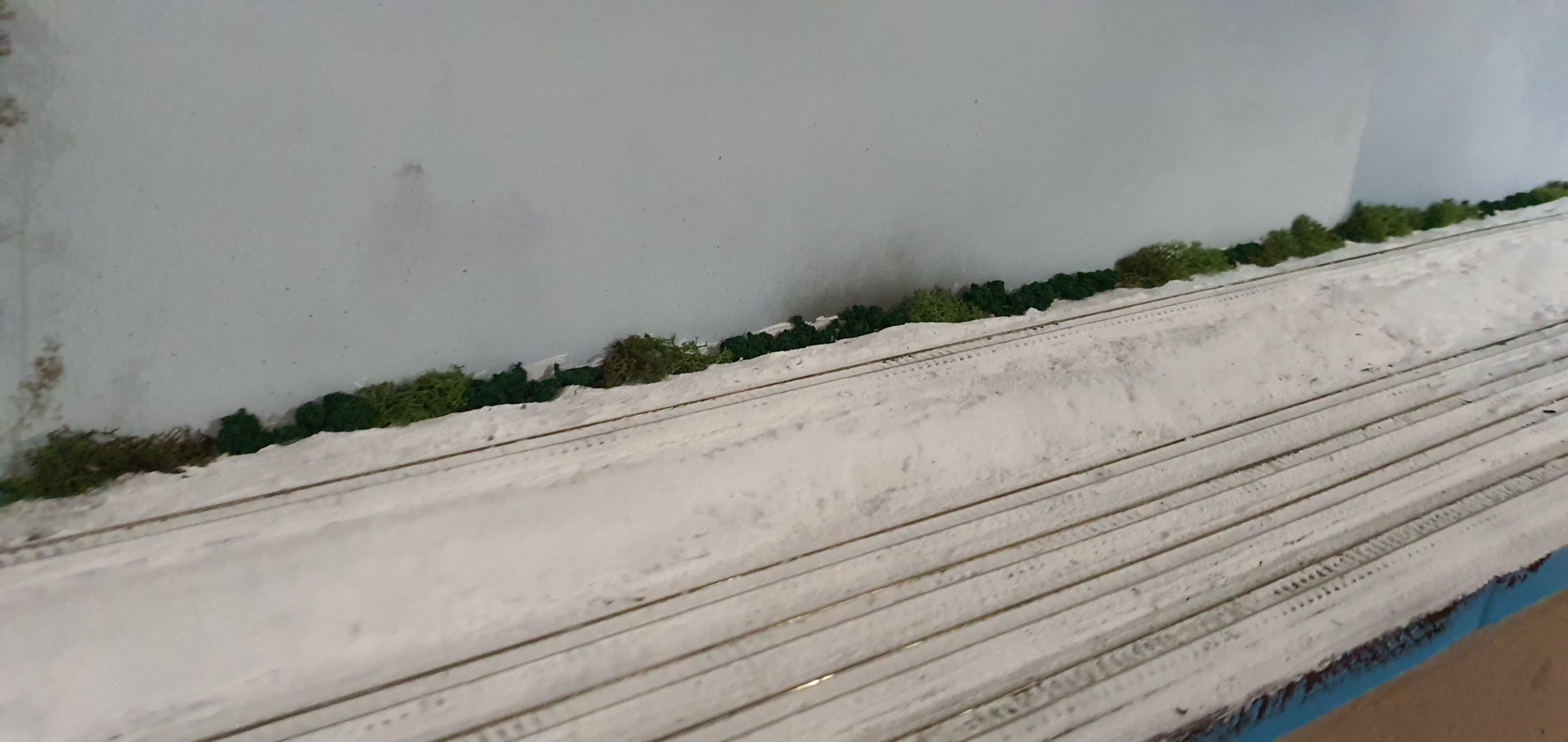
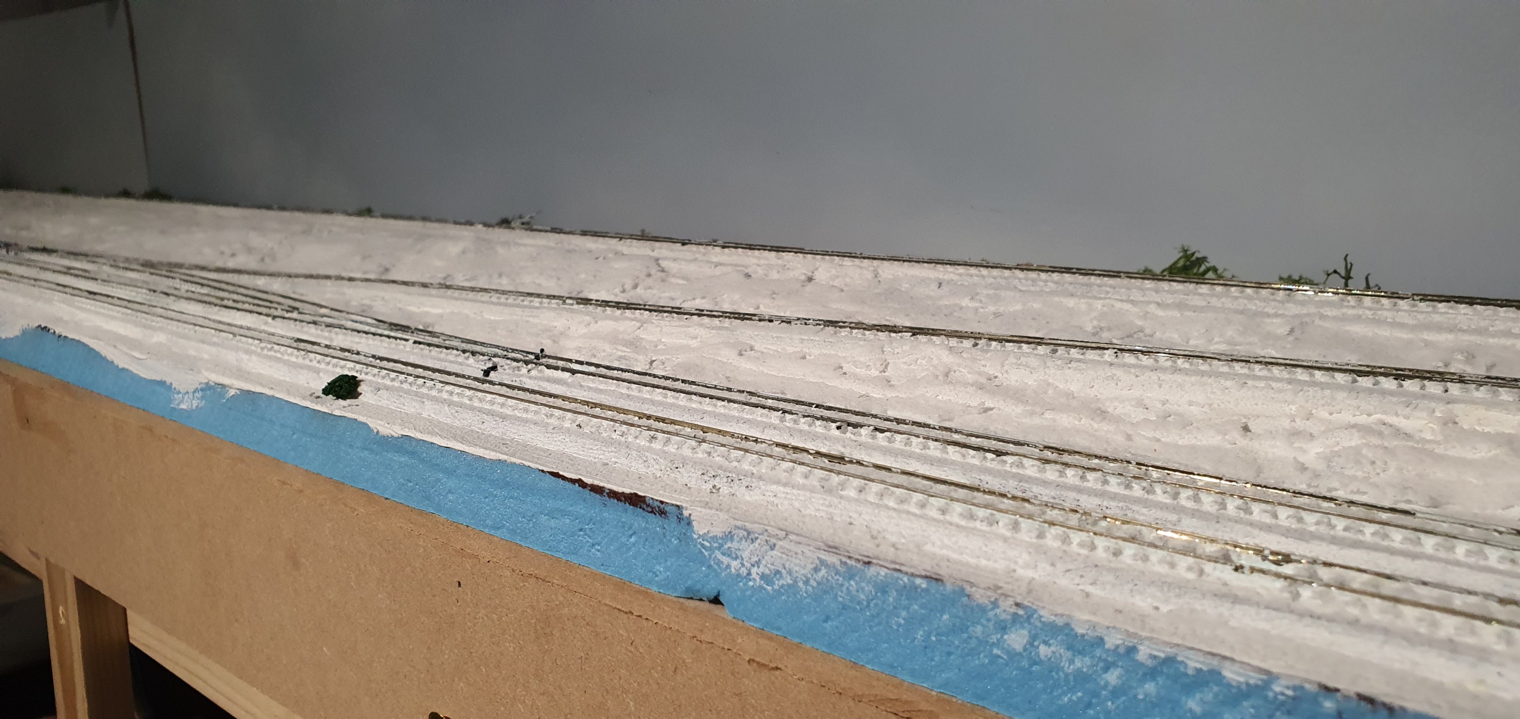
Well tune back in tomorrow hopefully that sculptamold we did has dried enough for some paint. It looks far too blue over there.