
At the south end of Ackerville there is a highway overpass that crosses all the tracks. To model this overpass I used a Rix Products modern highway overpass kit. It is narrower than the prototype but the whole Ackerville area is compressed by 25-50% so having a narrower bridge still fits in the scene.
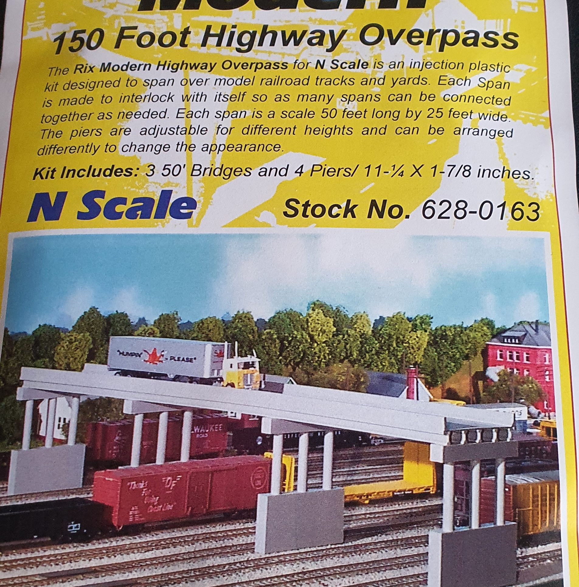
Lets have a look at what is in the packet.
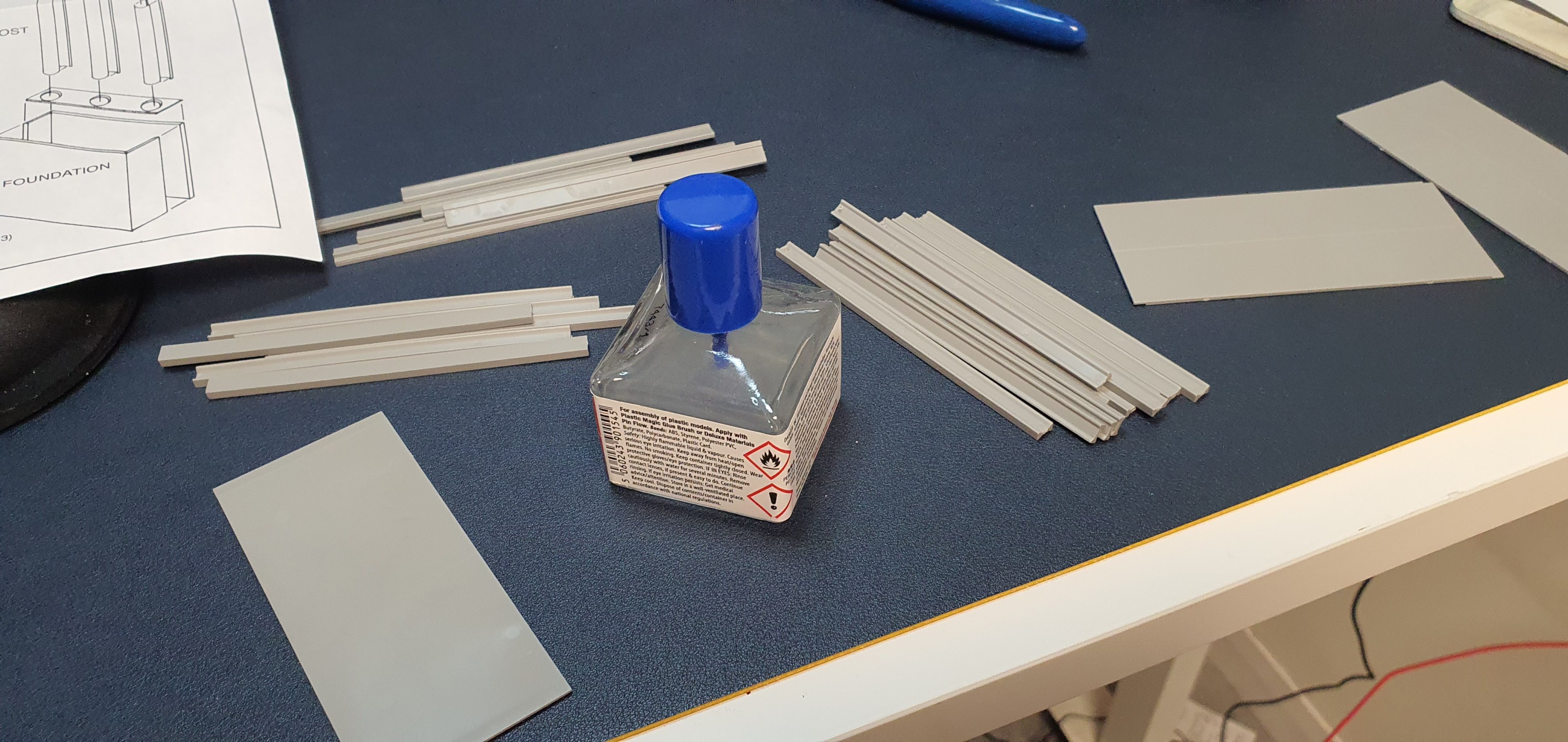
The first thing to do with the kit is to cut and file the girders from the sprues and seperate them. Here you see the I beams, C beams and barriers. The bridge decks each have three I beamsn and two C beams under each 50ft section.

The I beams go in first and then the C beams between each I beam.
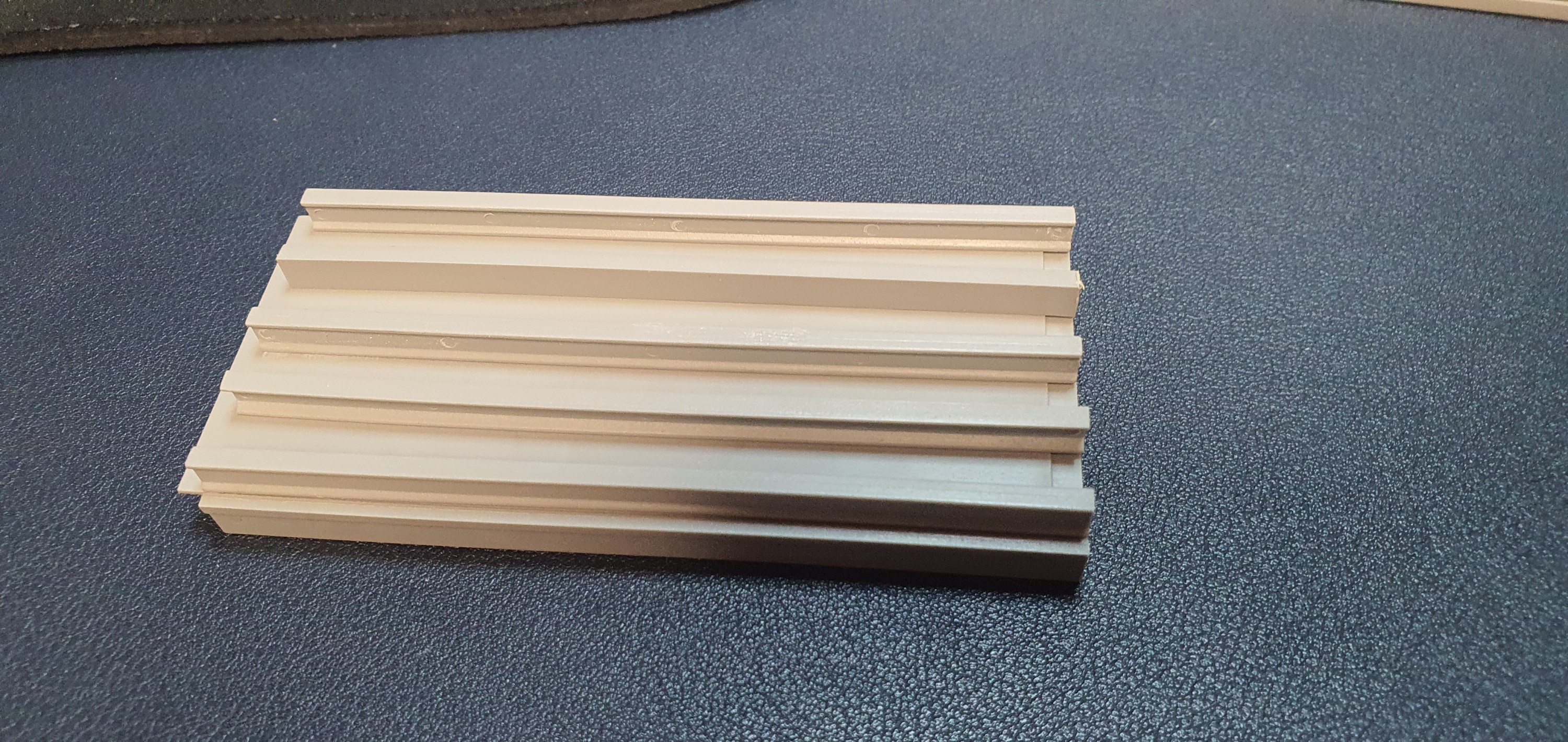
If the bridge is being assembled in one piece then I would suggest that you glue the road deck sections together on a flat surface and then line the beams up on each section.
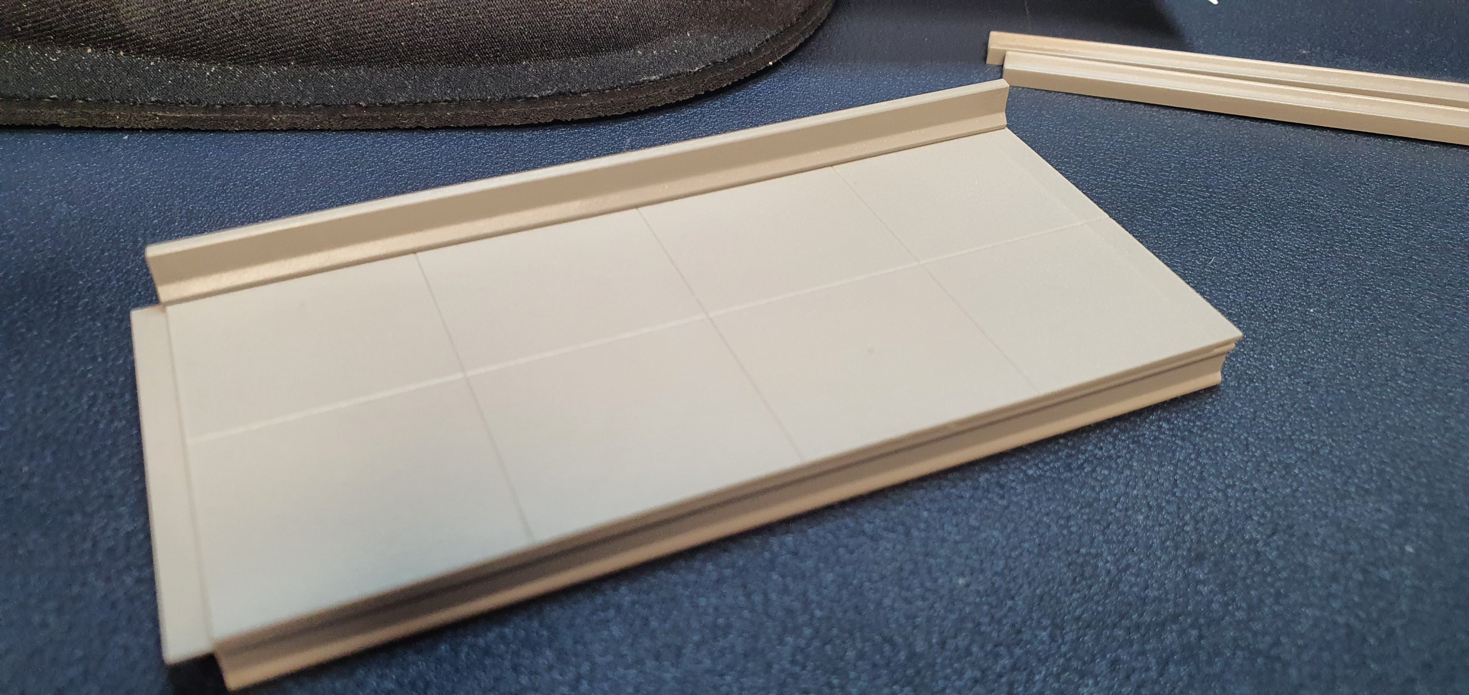
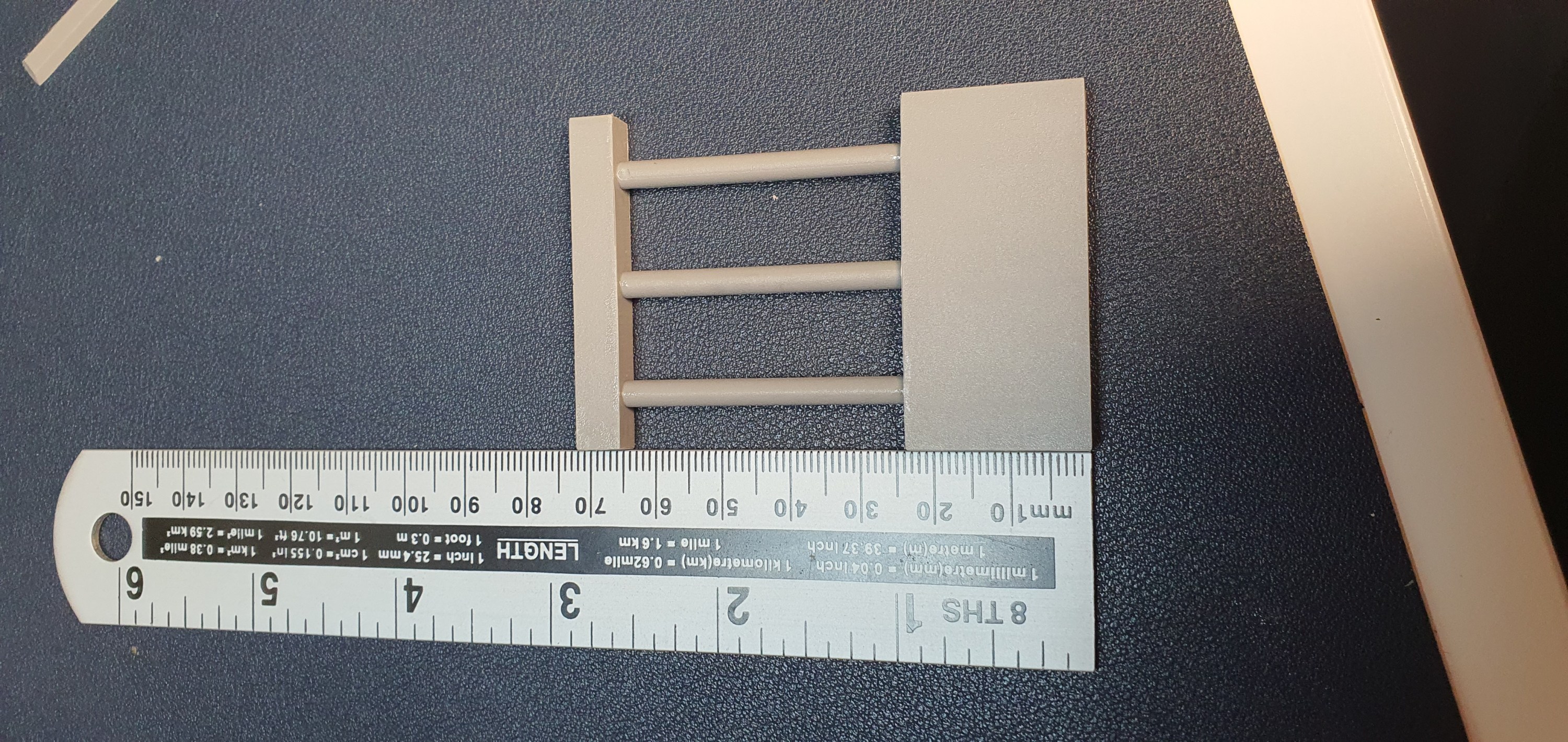
Then I added the crash barriers to the edge of the roadway.
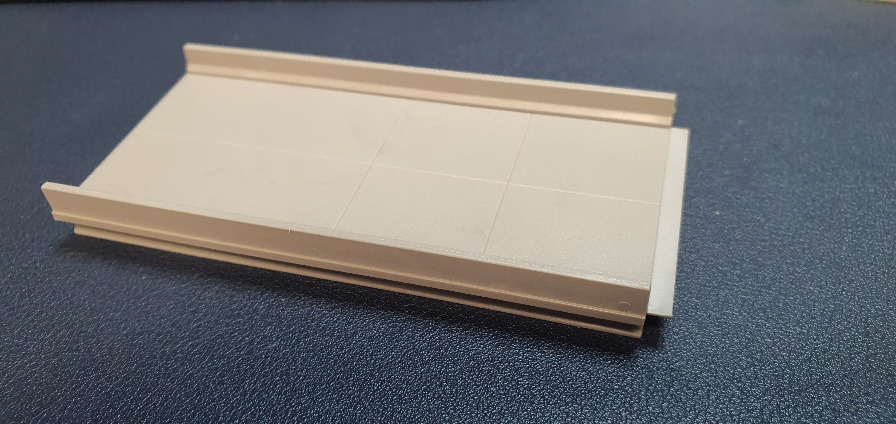
Here is a completed 50′ bridge section
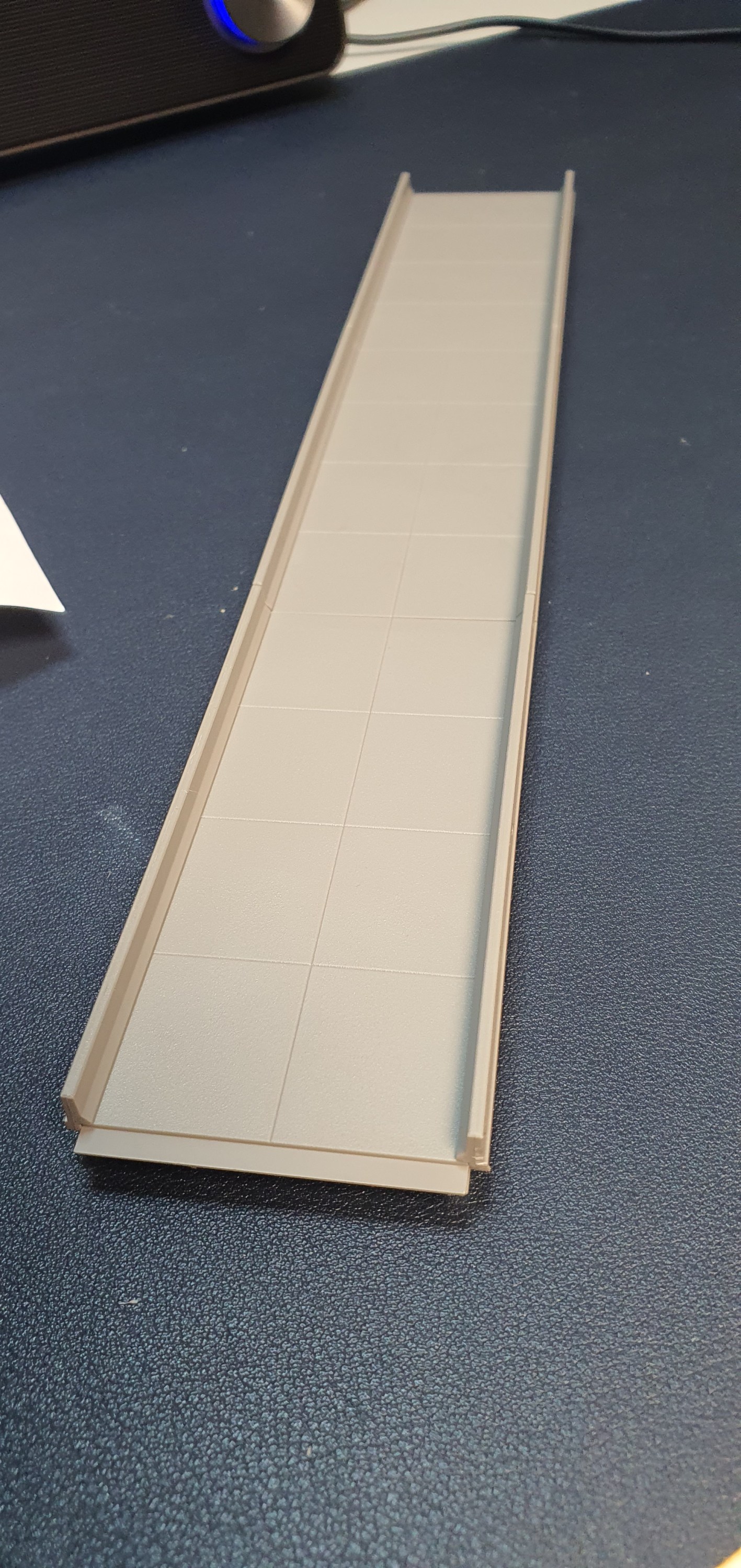
The completed 150′ of bridge deck. So time for the piers.
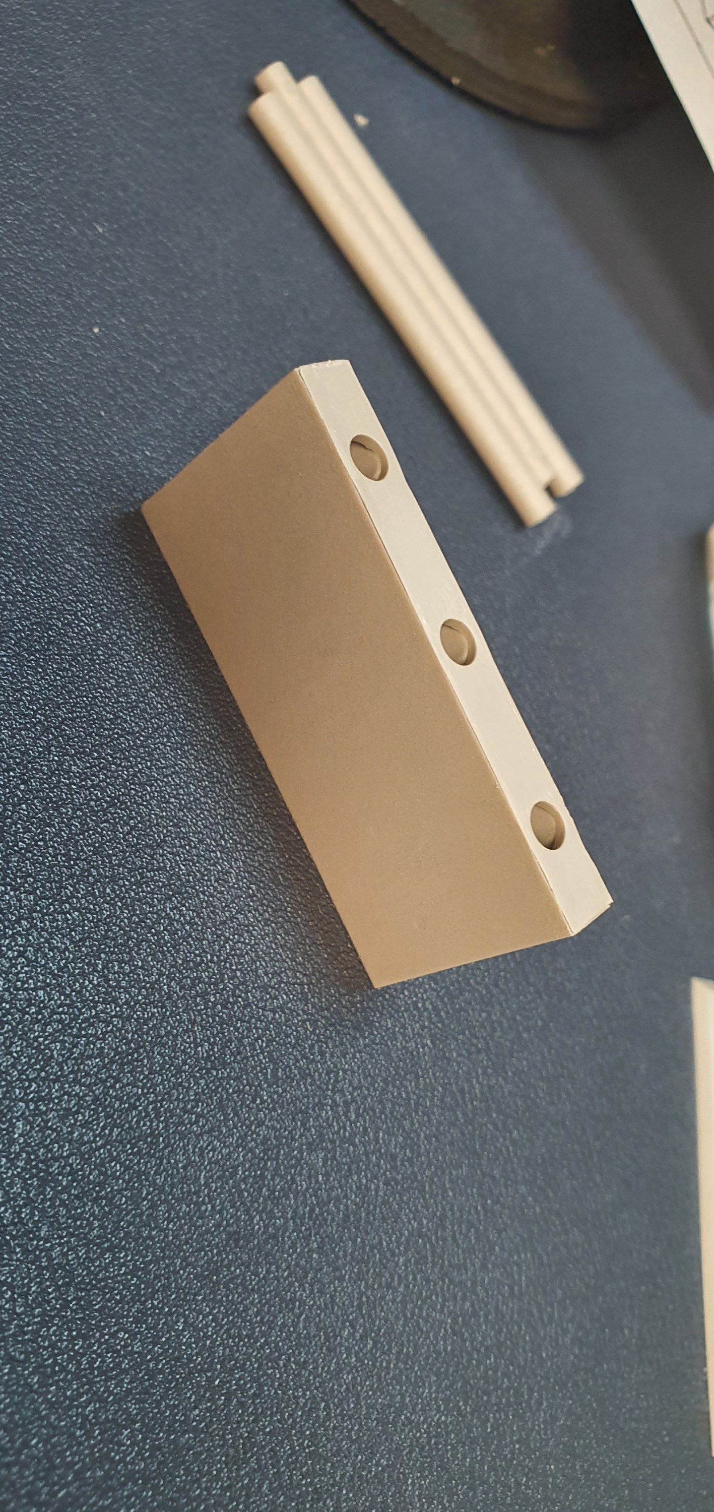
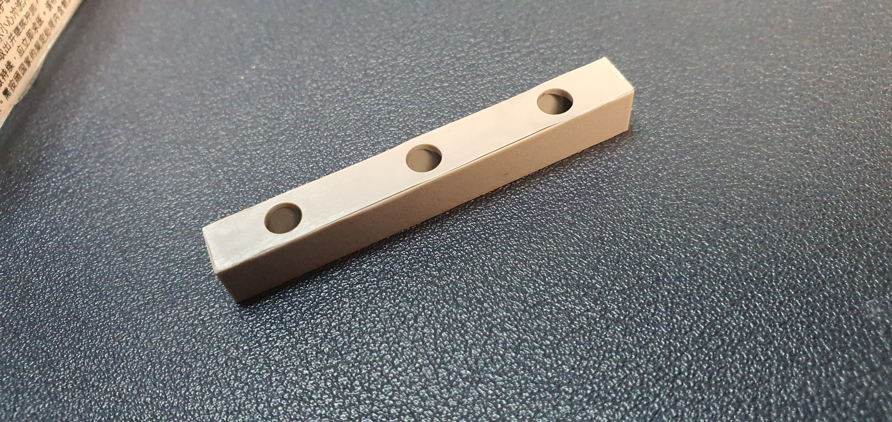
Start by assembling the upper and lower sections of each pier and then measure the hight you need the bridge to be. Now on this section of Ackerville the WSOR is 20mm higher than the CN mainline so I want my bridge to be 70mm above the CN mainline.
Once I was happy with the hight of the piers I glued the posts into place.

Done, but lets get it on the layout and test everything before we take it to the paint booth in part two.

This looks awesome, well yeah I am biased and I know its nothing like the actual bridge in Ackerville but no one in Orkney will have seen the real bridge. By making the deck solid I am able to offset the piers to allow for a larger gap between the piers on the WSOR section and narrower for the CN.
Ok I see the middle pier is too low but we’ll get that fixed before final installation. right I don’t know when part two of this builld will be getting some paint and weathering on it and we’ll get it installed.
See you all tomorrow,
Gordy
