
we have had quite a few deliveries this week, unfortuantley the weather has delayed the cargo boat so I am still waiting for the tools needed to cut the rest of the benchwork items. Thats not going to stop some progress though so a quick hour of work saw Ackerville tidyed up and the track, subroad bed and foam used to plan the scnery for that area was all tidyed away.

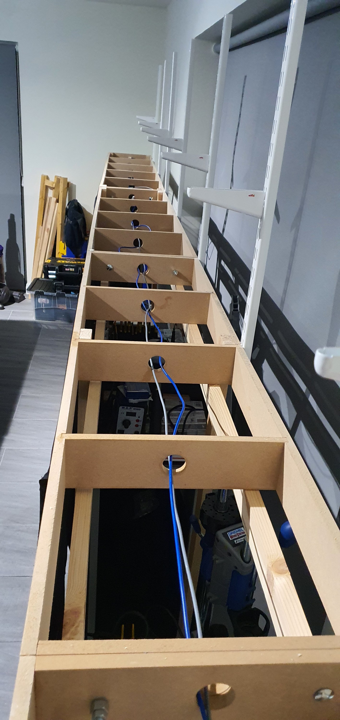
That exposed the module frame which allowed me to install the DCC Bus wire. I am using some seriously overkill wire here at 2.5mm but its got to carry alot along the DCC Bus so its not the area to skimp on. The Bus will be connected to the electrical boards we prepared earlier using T-tap connections so all I needed to fit is a bus along each module. I am focusing on getting the first part of the layout finished so that means about 29 feet of layout needs to be worked on to a finished state first. Anyway enough explaining here is a wee timelapse for you I know how much you enjoy them.
There wil be a follow up to this when we move onto the yard area of the lower deck (the bit still with loads of stuff on it. There is lots going on this weekend so who knows what will be posted tomorrow. Stay Tuned.
Gordy

I’ve just got some of those connectors, 3 pole for turnout motors. For my DCC bus I’m using Wago, they hold much tighter but are only single pole, I’ll have 5 way ones placed around the layout to split off for the track. The Wago 221 series are easier to use and take a better range of wire size for us.
LikeLike